


10
Front and Rear Panels
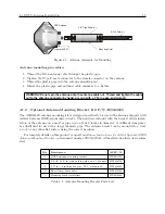
2.3.7
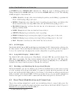
Standard Inputs/Outputs
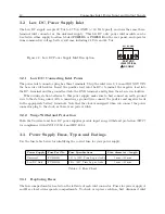
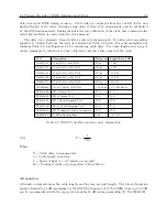
Figure 2.9 illustrates the timing input/output connectors available for multiple purposes including
modulated IRIG-B, unmodulated IRIG-B, 1 PPS, programmable pulse, open drain pull down and
event input. For information on driving multiple devices connected in parallel from a single output
connector, see Chapter 9, Timing, IRIG-B and Pulses.
Figure 2.9: Standard Input/Output Connectors
I/0 PORTS
+ - + - + -
1 2 3
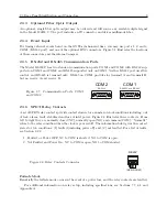
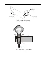
2.3.8
Option Board Interface
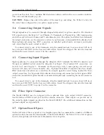
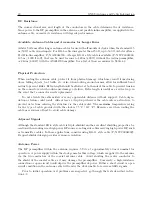
Figure 2.10 illustrates the left side of the rear panel where a panel covers space for an option board
connectors. When an option is installed, there will be one or more connectors and labels to identify
purpose. The clock serial number is shown to the left of the option panel.
Figure 2.10: Option Board Interface
B1234
Arb
it
e
r Sy
st
e
m
s
Serial Number
Made in USA
OPTION PANEL
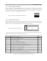
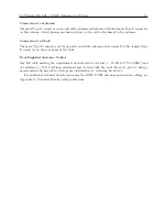
Each of these options are defined and covered in detail in Appendix B, Options List, at the
pages listed in Table 2.1 below. Current options include:
Option No.
Option Board Description
Page
E01
Four Additional Configurable Outputs
E02
Four Fiber Optic Outputs
E03
Eight-Channel, High Drive IRIG-B Outputs
E04
Power System Time, Frequency and Phase Monitor
E05
Four Additional Outputs with Dry Contacts and +25/50 Vdc
E06
NTP/PTP Server – Copper/Copper Ports
E07
NTP/PTP Server – Copper/Fiber Ports
E08
NTP/PTP Server – Fiber/Fiber Ports
E09
Four BNC Connectors (Parallel to Pluggable Terminal Strip)
Table 2.1: Option Boards, Descriptions and Locations
Summary of Contents for 1201B
Page 4: ...iv ...
Page 153: ...B 7 Four Fiber Optic Outputs 135 Figure B 4 Jumper Locations ...