


24
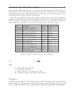
Setting Internal Jumpers
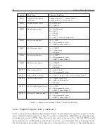
Jumper
Function
Jumper Position
JMP1
Normal/Demo Mode
Selection
Jumper removed = Normal mode*
Jumper placed = Demo Mode
JMP2
RS-485 source select
A = Data out*
B = IRIG-B
JMP4
Event source select
A = RS-232 port
B = Port 1
C = Port 2
D = Port 3
E = Port 4, external connector*
JMP6
Port 1 signal select
A = 1 PPS
B = Programmable pulse
C = IRIG-B unmodulated*
JMP7
Port 1 source select
A = CMOS*
B = Open drain
C = Event in
JMP8
Port 3 signal select
A = 1 PPS*
B = Programmable pulse
C = IRIG-B unmodulated
JMP9
Port 3 source select
A = CMOS*
B = Open drain
C = Event in
JMP10
Relay source select
A = Out of lock*
B = Programmable pulse
JMP11
Relay COM selection
A = Direct*, or B = user selects resistor (R24)
JMP12
Port 2 source select
A = Digital signal out
B = IRIG-B modulated*
C = Event in
JMP13
Port 2 digital signal select
A = 1 PPS
B = Programmable pulse
C = IRIG-B unmodulated*
JMP14
Fiber port function select
A = 1 PPS
B = Programmable pulse
C = IRIG-B unmodulated*
Table 5.1: Main board Jumper Table (*default positions)
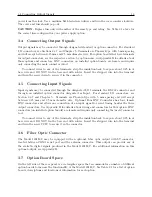
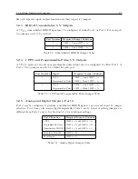
5.2.2
Digital Outputs: Port 1 and Port 3
Ports 1 and 3 provide identical digital signal choices, and setting their respective jumpers are the
same. Available digital signals from these two ports are unmodulated IRIG-B, programmable pulse
and pulse per second (1 PPS). These two ports may also be jumper-ed to a 200 volt FET for pull
down applications. Additionally, each port may be used as an event input. One set of jumpers sets
the type of signal and another set of jumpers sets the signal source. Tables on the following pages
Summary of Contents for 1201B
Page 4: ...iv ...
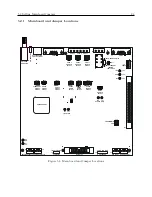
Page 153: ...B 7 Four Fiber Optic Outputs 135 Figure B 4 Jumper Locations ...


