


64
Front Panel Menu System
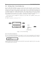
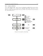
8.1.6
Configuration Flow Diagrams
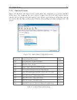
This section explains how to use the setup menu flow diagrams in the following sections. The LCD
screens display contents of each menu. Use the lower row of keys to configure clock settings.
1. Always start configuring by pressing SETUP.
2. Scroll through the menus using either UP or DOWN.
3. When you see the specific menu to configure, press ENTER to start configuring.
4. Once in the individual menu, use UP or DOWN to make selections.
5. To configure numerical values, see Section 8.1.7 below.
6. Press ENTER to install the new value and move to the next menu.
7. Press any of the upper row of keys to exit the configure menus.
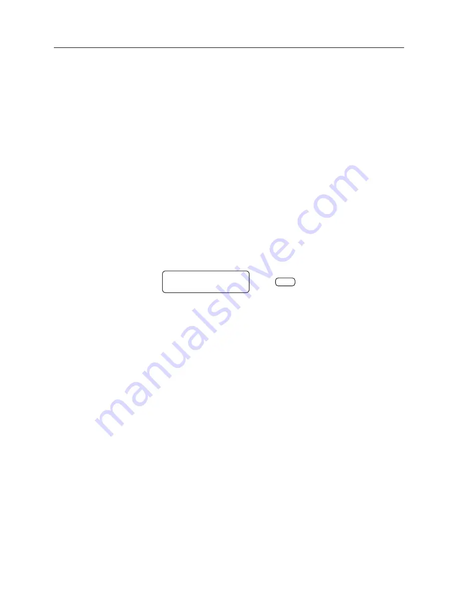
The figure below illustrates two elements of the setup menu flow chart: a larger rounded rect-
angle and a small oval. The larger rounded rectangles represent messages within the clock LCD
display, and the small oval symbol represents the individual keys of the eight-button keypad.
KEY
DISPLAY MENU
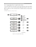
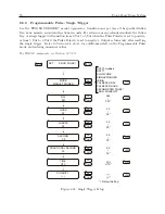
8.1.7
Numeric Data Entry Mode
Numeric data entry mode is activated anytime you enter a menu that requires a change in numerical
value. When in this mode, press UP or DOWN to change the numerical value of the digit. Next,
press SETUP or ENTER to move the cursor to the left or right. Keep moving along in this manner
changing all the required digits to complete the whole number. Press ENTER at the end to move
the cursor to the right, and finally to store the number.
Summary of Contents for 1201B
Page 4: ...iv ...
Page 153: ...B 7 Four Fiber Optic Outputs 135 Figure B 4 Jumper Locations ...


