Installation
- 13 -
FAN2 : FAN Connector
Type: onboard 3-pin wafer connector
Pin
1
2
3
Description
GND
+12V
Fan_Detect
Installation
- 14 -
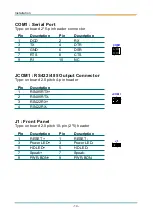
COM1 : Serial Port
Type: onboard 2*5-pin header connector
JCOM1 : RS422/485 Output Connector
Type: onboard 2.0pitch 4-pin header
J1 : Front Panel
Type: onboard 2.0pitch 10-pin (2*5) header
Pin
1
3
5
7
9
Pin
1
2
3
4
Pin
1
3
5
7
9
Pin
1
3
5
7
9
Description
DCD
TX
GND
RTS
RI
Description
R
RS485RTX-
RS422RX-
Description
RESET +
Power LED+
HD LED+
Speak+
PWR-BON+
Description
RESET -
Power LED-
HD LED-
Speak-
PWR-BON-
Description
RX
DTR
DSR
CTS
NC
Pin
2
4
6
8
10
Pin
1
3
5
7
9
11
13
15
17
19
21
23
25
27
29
31
33
35
37
39
Description
IDE RESET
DATA7
DATA6
DATA5
DATA4
DATA3
DATA2
DATA1
DATA0
GND
HD_DREQ
HD_IOW
HD_IOR
HD_RDY
HD_DACK
IRQ
ADDR1
ADDR0
HD_CS0
HD_ACT
Pin
2
4
6
8
10
12
14
16
18
20
22
24
26
28
30
32
34
36
38
40
Description
GND
DATA8
DATA9
DATA10
DATA11
DATA12
DATA13
DATA14
DATA15
NC1
GND
GND
GND
NC2
GND
NC3
NC4
ADDR2
HD_CS1
GND
IDE1 : Enhanced IDE Connector
Type
onboard 40-pin 2.54mm box headers
IDE
FAN2
COM1
JCOM1
J1
Summary of Contents for EmCORE-v7002
Page 1: ......
Page 2: ...EmCORE v7002 VIA Eden 3 5 Embedded Board User s Manual Version 1 0 2008 04...
Page 4: ...Introduction 1 Introduction 1 Chapter 1...
Page 10: ...1 11 Board Dimensions Introduction 7...
Page 11: ...Installation 2 Chapter 2 Installation 8...
Page 22: ...BIOS 19 BIOS 3 Chapter 3...


