background image

- 1 -

Introduction

1

Chapter 1

Introduction

Summary of Contents for EmETXe-i88U4-D1508

Page 1: ...EmETXe i88U4 COM Express Compact Type 6 CPU Module User s Manual Version 1 0 2020 07...

Page 2: ...Revision History Version Date Description 1 0 2020 07 Initial release...

Page 3: ...4 Inside the Package 4 1 5 Ordering Information 4 1 5 1 Optional Accessories 4 Chapter 2 Board Overview 7 2 1 What Is COM Express 8 2 2 Board Dimensions 9 2 3 Block Diagram 10 2 4 Connector Pin Defin...

Page 4: ...sor Configuration 32 4 3 2 Advanced Power Management Configuration 33 4 3 3 QPI Configuration 36 4 3 4 Memory Configuration 40 4 3 5 PCH Configuration 41 4 4 Security 46 4 5 Boot 47 4 6 Save Exit 48 A...

Page 5: ...iance with the directives of the Union European EU A Certificate of Compliance is available by contacting Technical Support This product has passed the CE test for environmental specifications when sh...

Page 6: ...ectronic Equipment RoHS Directive 2002 95 EC The above mentioned directive was published on 2 13 2003 The main pur pose of the directive is to prohibit the use of lead mercury cadmium hexava lent chro...

Page 7: ...r on the bag that comes with the Single Board Computer whenever components are separated from the system Replacing the Lithium Battery Incorrect replacement of the lithium battery may lead to a risk o...

Page 8: ...of or inability to use this product Vendor will not be liable for any claim made by any other related party Vendors disclaim all other warranties either expressed or implied including but not limited...

Page 9: ...1 Introduction 1 Chapter 1 Introduction...

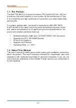
Page 10: ...ace conscious CPU board of 95 mm x 95 mm to take up only small footprint in your system By the architecture of Type 6 the board has two high performance connectors to promise stable data passing rate...

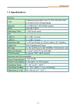
Page 11: ...ports Expansion Bus 1 x PCIex16 lane 8 x PCIex1 lanes I2C Interface Digital I O 8 bit Digital Input Output Storage 4 x Serial ATA ports with 600MB s HDD transfer rate Ethernet Chipset 1 x Intel i210I...

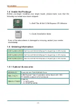
Page 12: ...mmediately 1 5 Ordering Information EmETXe i88U4 D1539 Intel Xeon D1539 COM Express Compact Type 6 CPU module EmETXe i88U4 D1508 Intel Xeon D1508 COM Express Compact Type 6 CPU module EmETXe i88U4 D15...

Page 13: ...ease contact your Arbor Sales Representative to get the permission to visit our website at www arbor technology com and download the driver pack from the product page Driver Path SERVER EmETXe i88U4 S...

Page 14: ...6 This page is intentionally left blank...

Page 15: ...7 Board Overview 2 Chapter 2 Board Overview...

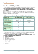
Page 16: ...s a Type 6 module Difference between Standard Type 6 and EmETXe i88U4 is listed as below Module Type Standard Type 6 EmETXe i88U4 Connectors 2 2 Connector Rows A B C D A B C D PCIe Lanes Max 24 24 LAN...

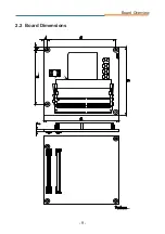
Page 17: ...9 Board Overview 2 2 Board Dimensions...

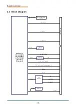
Page 18: ...e0 3 configurable to x4 LPC I F SMBus 8 x USB 2 0 Ports 4 x SATA 600Gb s ports SPI Bus SPI Bus SPI BIOS 2 x UART 8 bit GPIO I2C LPC I F ITE IT8528VG 1 x PCIex16 2 x PCIex1 Connector AB DDR4 2133MT s E...

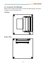
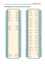
Page 19: ...11 Board Overview 2 4 Connector Pin Definition Top Side Bottom Side Being a most commonly used Type 6 the EmETXe i88U4 features two board to board connectors on bottom side DIMM1 2 DIMM2 2...

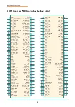
Page 20: ...SB_OC3_N A38 USBDN2_DN A39 USBDN2_DP A40 GND A41 USB_2N A42 USB_2P A43 USB_OC1_N A44 USB_0N A45 USB_0P A46 VCC_RTC A47 PLTRST _BUFF A48 EXCD0_CPPE A49 SERIRQ A50 GND A51 PCIE_TXP6 A52 PCIE_TXN6 A53 DI...

Page 21: ...61 PE1_TX_DP_3 D62 PE1_TX_DN_3 D63 N C D64 N C D65 PE1_TX_DP_4 D66 PE1_TX_DN_4 D67 N C D68 PE1_TX_DP_5 D69 PE1_TX_DN_5 D70 GND D71 PE1_TX_DP_6 D72 PE1_TX_DN_6 D73 GND D74 PE1_TX_DP_7 D75 PE1_TX_DN_7 D...

Page 22: ...14 This page is intentionally left blank...

Page 23: ...15 Installation Maintenance 3 Chapter 3 Installation Maintenance...

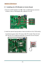
Page 24: ...COM Express connectors as below that is COM Express AB to AB and CD to CD AB connector CD connector 2 Install the optional heat spreader or heat sink with fan to the COM module Apply thermal grease to...

Page 25: ...17 Installation Maintenance Then connect the fan cable to the fan connector on the carrier board...

Page 26: ...18 This page is intentionally left blank...

Page 27: ...19 BIOS 4 Chapter 4 BIOS...

Page 28: ...set Boot Security Save Exit BIOSName BIOS Version Build Date and Time Access Level EC Version Memory Information Total Memory System Date System Time EmETXe i88U4 1 02 04 01 2019 10 47 43 Administrato...

Page 29: ...the numeric value on a selected setup item make change Page Down Decrease the numeric value on a selected setup item make change F1 Activate General Help screen F2 Restore previous values F9 Load opti...

Page 30: ...Change Opt F1 General Help F2 Previous Values F9 Optimized Defaults F10 Save and Exit ESC Exit Advanced Chipset Security Save Exit Main Boot Setting Description Trusted Computing See 4 2 1 Trusted Co...

Page 31: ...faults F10 Save and Exit ESC Exit Advanced Configuration Security Device Support Enable No Security Device Found Enables or disables BIOS support for security device O S will not show Security Device...

Page 32: ...rial Port 1 CON1 Select Screen Select Item Enter Select Change Opt F1 General Help F2 Previous Values F9 Optimized Defaults F10 Save and Exit ESC Exit Advanced Aptio Setup Utility Copyright C 2019 Ame...

Page 33: ...e Fan1 Speed VCORE VCCDU VIN 37o C 5269 RPM 0 858 V 1 189 V 11 942 V Select Screen Select Item Enter Select Change Opt F1 General Help F2 Previous Values F9 Optimized Defaults F10 Save and Exit ESC Ex...

Page 34: ...stem will wake on the current time Increase minute s Select Screen Select Item Enter Select Change Opt F1 General Help F2 Previous Values F9 Optimized Defaults F10 Save and Exit ESC Exit Advanced Sett...

Page 35: ...it ESC Exit Advanced Aptio Setup Utility Copyright C 2019 American Megatrends Inc Version 2 19 1269 Copyright C 2019 American Megatrendes Inc Setting Description CSM Support Enable default or Disable...

Page 36: ...xecution of UEFI and Legacy Storage OpROM Options Do not launch UEFI default and Legacy Video Control the execution of UEFI and Legacy Video OpROM Options Do not launch UEFI and Legacy default Other P...

Page 37: ...Select Screen Select Item Enter Select Change Opt F1 General Help F2 Previous Values F9 Optimized Defaults F10 Save and Exit ESC Exit Advanced Enabled Disabled 20 sec 20 sec Auto Aptio Setup Utility C...

Page 38: ...are 10 sec 20 sec default 30 sec 40 sec Device power up delay Use this item to set maximum time the device will take before it properly reports itself to the host controller Options available are Aut...

Page 39: ...ESC Exit Processor Configuration Advanced Power Management Configuration QPI Configuration Memory Configuration PCH Configuration Main Advanced IntelRCSetup Setting Description Processor Configuration...

Page 40: ...or Configuration Processor Socket Socket 0 Processor ID 00050663 Processor Frequency 1 600GHz Processor Max Ratio 10H Processor Min Ratio 08H Microcode Revision 0700000E L1 Cache RAM 512KB L2 Cache RA...

Page 41: ...Item Enter Select Change Opt F1 General Help F2 Previous Values F9 Optimized Defaults F10 Save and Exit ESC Exit Advanced Power Management configuration EIST P states CPU P State Control CPU C State...

Page 42: ...le IntelRCSetup Setting Description Energy efficient P states Enable default or Disable Energy efficient P state feature When set to 0 will disable access to ENERGY_PERFORMANCE_BIAS MSR and CPUID func...

Page 43: ...ral Help F2 Previous Values F9 Optimized Defaults F10 Save and Exit ESC Exit CPU C State Control CPU C State Enable CPU C3 State Disable CPU C6 State Enable IntelRCSetup Setting Description CPU C Stat...

Page 44: ...Settings Select Screen Select Item Enter Select Change Opt F1 General Help F2 Previous Values F9 Optimized Defaults F10 Save and Exit ESC Exit QPI Configuration QPI Per Socket Configuration QPI Per S...

Page 45: ...sable C0D Enable Auto Home Dir Snoop with IVT Style OSB Auto QPI Debug Print Level All IntelRCSetup Setting Description QPI Status To view QPI status Degrade Precedence Choose Topology Precedence to d...

Page 46: ...isable default E2E Parity COD Enable Enable or Disable Cluster on Die Options Disable Enable and Auto default Early Snoop Enable or Disable early snoop Options Disable Enable and Auto default Home Dir...

Page 47: ...Save and Exit ESC Exit QPI Per Socket Configuration CPU 0 CPU 1 CPU 2 CPU 3 IntelRCSetup Setting Description Bus Resources Allocation Ratio Configure bus resources allocation ratio range 0 to 8 IO Res...

Page 48: ...rican Megatrendes Inc System Agent SA Parameters Select Screen Select Item Enter Select Change Opt F1 General Help F2 Previous Values F9 Optimized Defaults F10 Save and Exit ESC Exit Integrated Memory...

Page 49: ...F9 Optimized Defaults F10 Save and Exit ESC Exit PCH Configuration PCH State after G3 S0 PCI Express Configuration PCI SATA Configuration USB Configuration IntelRCSetup Setting Description PCH State...

Page 50: ...ot Port Function Swapping Didabled PCI Express Root Port 1 PCI Express Root Port 2 PCI Express Root Port 3 PCI Express Root Port 4 PCI Express Root Port 5 PCI Express Root Port 6 PCI Express Root Port...

Page 51: ...amically assin function 0 to enabled root port PCI Express Root Port 1 6 PCI Express Root Port Enable default or disable the PCI Express root port ASPM Disable or set the ASPM level Force L0s will for...

Page 52: ...PCH SATA Configuration SATA Controller Enabled SATA Port 0 Not Installed SATA Device Type Solid State Drive SATA Port 1 Not Installed SATA Device Type Solid State Drive SATA Port 2 Not Installed SATA...

Page 53: ...ol Disabled XHCI Idle L1 Enabled IntelRCSetup Setting Description USB Precondition Enable or Disable default preconditoin work on USB host controller and root ports for faster enmeration XHCI Mode Mod...

Page 54: ...d Exit ESC Exit Advanced Password Description Minimum length 3 Maximum length 20 Administrator Password Set Administrator Password IntelRCSetup Security Save Exit Main Boot Setting Description Adminis...

Page 55: ...Boot Option Priorities Boot Option 1 Select the keyboard NumLock state On Disabled MMC DG4032 Setting Description Boot NumLock State Select the keyboard NumLock state Options On default and Off Fast B...

Page 56: ...ESC Exit Main Boot Security Save Exit Setting Description Save Changes and Exit Exit system setup after saving the changes Enter the item and then a dialog box pops up Save configuration and exit Yes...

Page 57: ...49 Appendix Appendix...

Page 58: ...em automatically to avoid abnormal operation This board supports 255 levels watchdog timer by software programming I O ports Below are the source codes written in C please take them as WDT ap plicatio...

Page 59: ...0xBB Disable Watch Dog void WDT_Clear void outportb 0x66 0xBA Enable Watch Dog delay 2000 outportb 0x62 WDTCount Number is Watch Dog Down count number delay 2000 outportb 0x62 0x00 Minute is 1 count u...

Page 60: ...GPIOStatus printf Data 2x n iInput GPIOData 0x05 delay 30000 iInput GPIOStatus printf Data 2x n iInput return 0 void GPIOMode int iMode outportb 0x66 0xEB Select DIO pin to output or input delay 2000...

Reviews: