background image

Use and Maintenance Manual

Page 16

4.2.  MOVEMENT AND TRANSPORT

If the machine needs to be transported over a long distance, 

it can be loaded onto a truck or other form of transport.

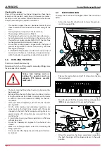
When moving the machine, lift it using a hoist or suitable 

crane with sufficient lifting capacity. The coupling points can 

be identified by the symbol 

“lifting point”

.

• 

Machine loading and unloading operations can be dan-

gerous unless carried out with extreme care. Ensure that 

there are no unauthorised persons in the area. Clear the 

loading and unloading area and ensure it is cordoned off.

• 

Ensure that the means available are suitable and intact. 

• 

Ensure that the working area is clear and there is a suit-

able "escape route", namely, a clear safe area the opera-

tors can reach immediately should the machine fall.

• 

Ensure operators are wearing suitable PPE, suitable 

clothing and the protections indicated (gloves, protec-

tive shoes, helmet, etc.).

• 

The surface where the machine is to be loaded/unload-

ed must be perfectly level to prevent the risk of the load 

moving unintentionally.

• 

When moving the machine, lift it by hooking it to the 

designated connections using a hoist or suitable crane 

with sufficient lifting capacity.

During transfers, connect all the 

safety devices.

During maintenance, connect all 

the safety devices and adopt all 

necessary precautionary mea-

sures to ensure personal safety.

Fig. 6


4.3.  DRIVING ON A PUBLIC ROAD

If it is necessary to drive on a pub-

lic road, it is mandatory to strictly 

respect the relevant highway code, 

paying particular attention to the 

speed.

When driving on the road, respect 

the relevant highway code for the 

specific country.

Any accessory used for transporta-

tion must be equipped with specific 

signals and adequate protective de-

vices.

• 

Before starting to drive, install any optional light bars.

• 

It is mandatory to equip the machine with a yellow or 

orange flashing light.

• 

Check the tyre pressure and restore the pressure if nec-

essary.

• 

Check that the towing eyelet of the seeder and the tow 

hook of the tractor have been coupled correctly.

• 

Check that the female plate connection (FLAT-FACE) is 

always connected to the tank return before moving the 

machine.

• 

Before starting to drive on a public street from a non-

paved or dirty surface, the tractor wheels must be 

cleaned carefully and nay mud present must be re-

moved.

• 

When driving on a public street, the machine must be in 

the transport position and the power socket of the trac-

tor must be unplugged.

• 

The weight of the machine modifies the stability of the 

combination tractor-seeder, influencing the steering 

ability as well as the breaking ability, it is thus important 

to proceed with a moderate speed.

• 

It is very important to remember that road-holding and 

steering and braking abilities may be influenced, even 

heavily, by the presence of any equipment which is be-

ing carried or towed.

• 

On bends, pay particular attention to the centrifugal 

force on the machine with or without the carried equip-

ment, especially on sloping streets or terrain.

• 

For transportation, set and fix the chains on the lifting 

side arms of the tractor; verify that the lids on the seed 

and fertiliser tanks are well sealed; put the control lever 

on the hydraulic lifter in the blocked position.

• 

Transport outside the working area must be carried out 

with the equipment in transport position. This also im-

plies that all hydraulic connection must be unplugged 

from the tractor.

Summary of Contents for MEK-X250

Page 1: ...MEK X Code 58310241 Rev 00 58310241 Translationoftheoriginalinstructions LOVOL ARBOS GROUP S p A a s u Via Canale 3 41012 Migliarina di Carpi Modena Italy T 39 0522 640111 F 39 0522 699002 info lovole...

Page 2: ......

Page 3: ...ONS 19 6 3 ELECTRICAL CONNECTIONS 19 6 4 STARTING UP THE MACHINE 19 6 5 SOWING 19 6 6 REFILLING THE TANK 20 6 7 SEED TANK DRAIN 20 6 8 LOW LEVEL SENSOR 21 6 9 DETACHING FROM THE MACHINE 21 7 ADJUSTMEN...

Page 4: ...Use and Maintenance Manual...

Page 5: ...t accompany it if it is resold and until it is de stroyed In case of loss or damage to this manual request a new copy from the manufacturer insert manufacturer s name address and telephone number or f...

Page 6: ...2 2 WARRANTY INVALIDATION Besides the indications provided in the supply contract the warranty is invalidated in the following cases If the limits referred to in the technical data table or in other t...

Page 7: ...sion wheel 3 Seed tank 4 Seed level sensor in hopper 5 Towbar 6 Support feet 8 13 12 1 4 5 10 11 6 2 3 1 9 7 1 1 7 Transport table light kit 8 Tank loading system with footboard 9 Seed collecting tray...

Page 8: ...achine has been designed and constructed exclusively for sowing on soil It can be coupled with any tractor equipped with a tow hook compliant with standards and with a minimum power as specified in th...

Page 9: ...sh cables ropes chains pipes etc Good machine operation is ensured by the correct use and suitable maintenance of the machine itself To ensure good operation and a long service life of the equipment i...

Page 10: ...50 17 140 255 470 540 625 50 420 7 50X16 69 18 130 480 550 645 MEK X 300 20 150 320 545 625 720 70 500 7 50X16 69 21 140 560 640 745 23 130 575 655 770 25 120 590 670 795 MEK X 350 25 140 350 660 740...

Page 11: ...ART AFTER A LONG PERIOD OF INACTIVITY Before using the machine for the first time or after a long pe riod of inactivity Verify that the machine has no damaged parts Check that the mechanical units are...

Page 12: ...t instructions please observe them to ensure your safety Make sure that the emergency pictograms are readable Clean them and replace them when necessary with new labels Before using the machine ensure...

Page 13: ...t is strictly prohibited to stand between the tractor and the machine with the engine on and cardan inserted Do not remove the protection grid inside the loading hopper in order to avoid risks of poss...

Page 14: ...anual Make sure that the emergency pictograms are readable Clean them using a cloth water and soap 4 1 1 LOCATION OF THE PICTOGRAMS Fig 5 4 1 2 DESCRIPTION OF THE PICTOGRAMS CAUTION The regulation and...

Page 15: ...Use and Maintenance Manual Page 15 CAUTION RISK OF TOXIC SUBSTANCES LIFTING POINT 58280011 TYRE PRESSURE CORRECT MACHINE ANGLE...

Page 16: ...ay code for the specific country Any accessory used for transporta tion must be equipped with specific signals and adequate protective de vices Before starting to drive install any optional light bars...

Page 17: ...machine make sure that no animals or people are standing within the working area it is strictly prohibited to take off and or modify the pro tective devices on the machine Do not use the machine when...

Page 18: ...draulic dis tributor with a relief valve calibrated to 180bar The equipment is particularly suited to direct sowing and sowing on land which has been prepared minimal tilling or traditional tilling Th...

Page 19: ...a single effect distributor with floating func tion YELLOW fan delivery to be connected to a priority dis tributor with flow control suitable for hydraulic motor actuation continuous flow approx 22 li...

Page 20: ...ator must use adequate PPE gloves overalls masks etc The tanks must be filled when the land to be sowed has been reached Before refilling the tank follow the instructions for calcu lating the minimum...

Page 21: ...ked must be flat and within a protected area so that only those authorized may approach it 7 ADJUSTMENTS To obtain correct seed density per hectare Kg Ha the distri bution organs must be properly adju...

Page 22: ...ellow slide gates N the settings for sow ing smaller seeds and smaller amounts will be modified The position of the slide gates ensures a regular flow of the seed into the distributor A B Fig 16 7 3 S...

Page 23: ...6 392 429 468 508 549 22 36 51 68 85 104 124 146 168 192 217 243 271 299 329 361 393 427 462 20 33 46 61 77 94 112 132 152 174 196 220 245 271 298 326 356 386 418 24 40 56 74 93 114 136 159 184 210 23...

Page 24: ...100 120 141 163 187 211 236 262 289 316 345 374 405 436 467 GEAR BOX POSITION 120 150 140 130 Kg Ha Interfila Spacing Ecartement Abstand Distancias Hileras mm m MEK X 250 MEK X 300 MEK X 350 MEK X 400...

Page 25: ...ion organs adjustment Type of seed OAT Use the large distribution roller W Set the plates to 4 A Set the feeler lever to position 1 Avena Oat Avoine Hafer Avena W 4 A 1 Semente Seeds Saargut Semence S...

Page 26: ...60 65 70 75 80 85 90 95 100 GEAR BOX POSITION 120 150 140 130 Kg Ha InInterfila Spacing Ecartement Abstand Distancias Hileras mm Segale Rye Seigle Roggen Centano 10 15 20 25 30 35 40 45 50 55 60 65 70...

Page 27: ...3 61 81 102 125 149 175 202 229 258 288 319 350 382 415 449 483 518 Interfila Spacing Ecartement Abstand Distancias Hileras mm Farro Spelled peautre Dinkel Espelta 10 15 20 25 30 35 40 45 50 55 60 65...

Page 28: ...95 100 GEAR BOX POSITION 120 150 140 130 Kg Ha 2 3 5 6 8 9 11 12 14 16 17 19 21 23 25 28 30 32 35 2 3 4 5 6 8 9 10 12 13 15 16 18 20 21 23 25 27 29 2 3 4 5 6 7 8 9 11 12 13 15 16 18 19 21 23 24 26 2...

Page 29: ...ls free to turn Act on the lever 14 at both ends to lower the grain de scent line support 16 14 16 Fig 18 Release the seed collecting trays 17 from the cover and position them below the seed outlets 1...

Page 30: ...ALF THE MACHINE In order to perform finishing jobs the machine is equipped with a system for excluding distributors on the right part of the ma chine from sowing To exclude he right part of the machin...

Page 31: ...oosen to reduce the sowing depth tighten to increase the sowing depth When the depth has been set remember to reposition the block 21 B Load Fig 22 In the case of a carrying machine raise the seeder f...

Page 32: ...ket as follows Loosen the screw 28 but do not remove it Remove the screw 29 Set the inclination of the adjustment bracket to the de sired position Insert the screw 29 to lock the bracket in position a...

Page 33: ...marker with line aligned with the centre of the tractor Dc Work width 7 9 2 ROW MARKER PREPARATION Park the tractor on level ground engage the handbrake ensure the seeder is raised above the ground a...

Page 34: ...G THE ROW MARKER DISC In the presence of more or less rugged lands adjust the row marker disc as follows Remove the screw 31 Position the disc as required Insert the screw 31to block the disc Repeat t...

Page 35: ...er than 1 50 m use ladders or platforms that comply with the regulations in force Do not carry out unfamiliar reparations Always follow in structions and where they are missing contact the man ufactur...

Page 36: ...U bolts in line with all the safety regulations sup plied with the product Check the inflation pressure of the tyres 8 2 FREQUENCY OF INTERVENTIONS Below you will find information on intervention time...

Page 37: ...companied by the following information machine type machine serial number spare part item code available from the spare parts catalogue The use of spare parts not approved by the manufacturer invalida...

Page 38: ...Use and Maintenance Manual Page 38...

Page 39: ...2006 42 EC repealing and replacing Directive 98 37 EC 2014 30 UE electromagnetic compatibility For models of machines with electrical electronic apparatus For machine compliance the following harmonis...

Page 40: ...This statement must be shown on request of the competent authorities To avoid that it becomes damaged or illegible it is recommended to cut down the hatch and place it in a protected place...

Page 41: ...Use and Maintenance Manual Page 39...

Page 42: ...Page 40 LOVOL ARBOS GROUP S p A a s u Via Canale 3 41012 Migliarina di Carpi Modena Italy T 39 0522 640111 F 39 0522 699002 info lovoleurope com lovolarbos com...

Reviews: