23
6. Temperature differential in external hot water tank heating mode: sets the hot water temperature
differential between the S4 boiler temperature probe and the S3 tank temperature probe. NOTE: the
hot water tank pump is started when the “Minimum boiler temperature” is reached. Furthermore, the
hot water preparation cycle starts when the temperature differential between the S4 high point boiler
probe and the S3 tank temperature probe reaches the “Temperature differential in hot water
preparation mode”. Example: Tank S3 temperature = 62 °C, temperature differential = 3 °C; the
pump is started when the boiler S4 temperature reaches 65 °C (62+3).
7. Temperature differential in solar panels heating mode: setting ON the solar panel function, this
parameter sets the solar panel system working temperature differential. The two involved probes are
S1 (solar panel probe) and S2 (hot water tank heat exchanger). To have heat transferred from the
solar panel system to the hot water tank heat exchanger the S1 temperature must be greater than
the heat exchanger S2 probe temperature by this value.
8. Boiler body maximum temperature differential: If the system delivery temperature is greater than that
of return by a difference greater than the value set by this parameter, the bypass pump will be started
to balance the temperature difference between the boiler highest and lowest point.
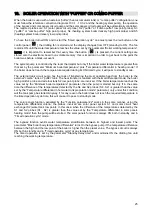
9. Standby delay time: Sets the "timed operation cycle" when the boiler is operative. The cycle
activation is performed by pressing the button (
); the drafting fan starts. If the boiler temperature
falls below the value “Minimum boiler temperature” (usually 60 °C), the boiler has the time set by this
parameter (usually 50’) to raise its temperature back above the said value, otherwise it will be cut off.
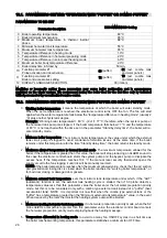
10. Function parameter #1 (probes activation/deactivation): See probes activation procedure description
(page16).
11. Function parameter #2 (optional setting): See optional settings description (page17).
12. Display language selection: See display language selection description (page17).
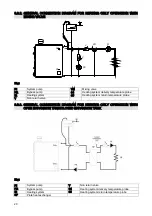
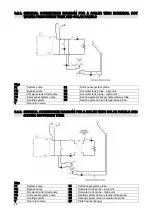
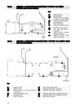
9.3. HYDRAULIC SCHEMATIC DIAGRAMS
All the schematic diagrams in this manual are given as reference only, and they must be validated by
authorized engineers. The company ARCA s.r.l. assumes no responsibility for any harm to objects, persons
and animals caused by a wrong system project. For any other schematic diagram you may need, feel free to
contact ARCA technical department. Putting in service heating systems realized differently from those
recommended in this manual, or otherwise not authorized, will cause void of warranty.
Note:
The correct operation of the boiler requires the bypass pump to avoid harmful water temperature
stratifications.
The absence of the bypass pump will void the warranty.


