background image


24

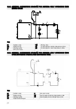
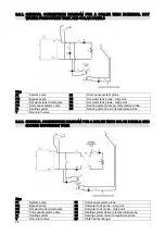
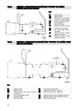
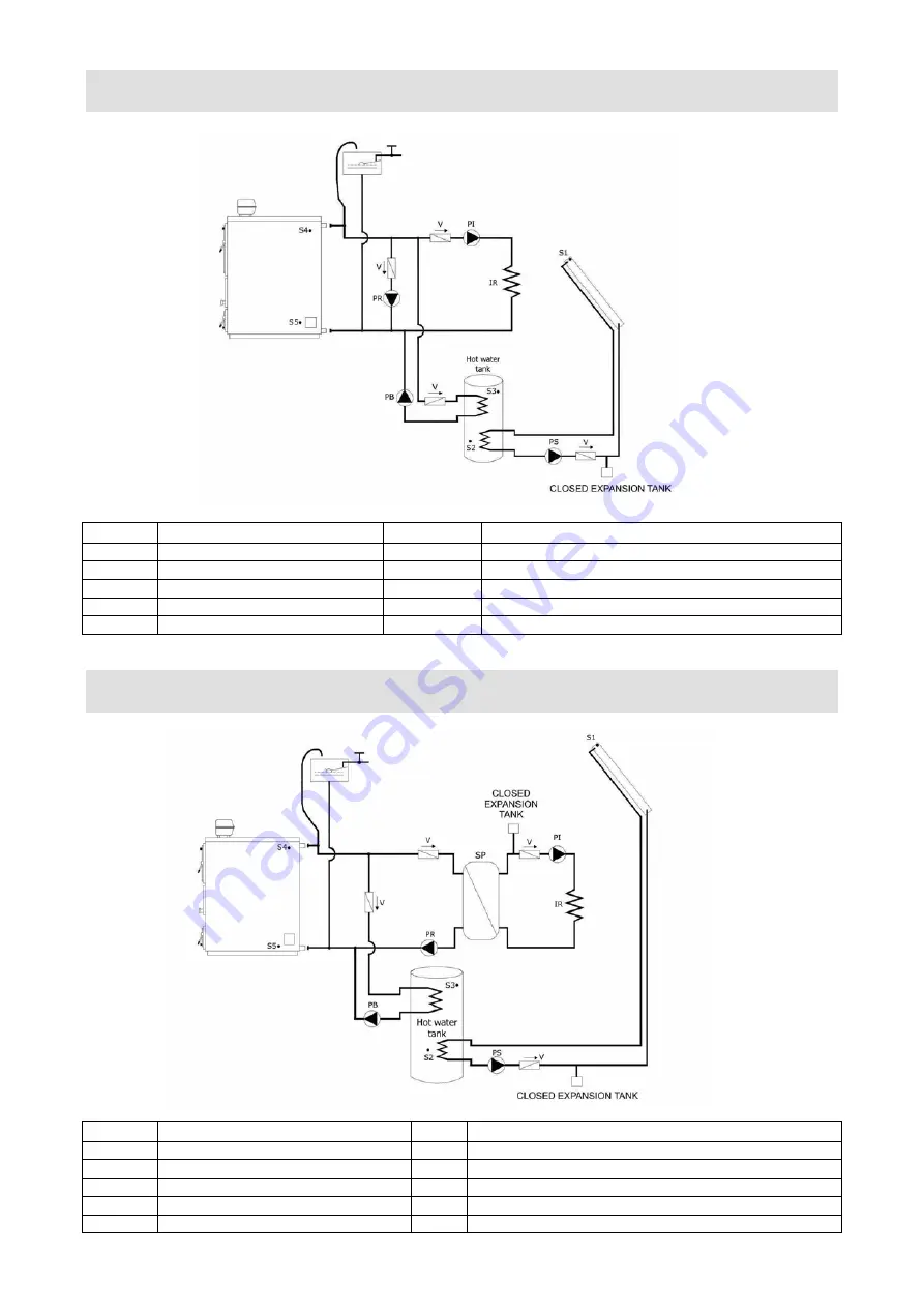
9.3.1. GENERAL CONNECTION DIAGRAM FOR A BOILER WITH EXTERNAL HOT 

WATER PRODUCTION TANK AND SOLAR PANELS  


Key: 

PI 

System pump 

S1 

Solar panel system probe 

PR 

Bypass pump  

S2 

Hot water tank probe - low point 

PB 

Hot water tank circuit pump 

S3 

Hot water tank probe - high point 

PS 

Solar panel system pump 

S4 

Heating system delivery temperature probe 

IR 

Heating system 

S5 

Heating system return temperature probe 

Non return valve 


9.3.2.  GENERAL CONNECTION DIAGRAM FOR A BOILER WITH SOLAR PANELS AND 
 CLOSED 

EXPANSION 

TANK 


Key: 

PI 

System pump 

S1 

Solar panel system probe 

PR 

Bypass pump  

S2 

Hot water tank probe - low point 

PB 

Hot water tank circuit pump 

S3 

Hot water tank probe - high point 

PS 

Solar panel system pump 

S4 

Heating system delivery temperature probe 

IR 

Heating system 

S5 

Heating system return temperature probe 

Non return valve 

SP 

Plate heat exchanger 

Summary of Contents for ASPIRO A 29 R/SA

Page 1: ...ASPIRO Installation Operation Maintenance www arcacaldaie com ...

Page 2: ...2 ...

Page 3: ...e future company ARCA reserves the right to apply modifications to its range of products should they be useful or necessary The present documentation is also available as PDF files Please fell free to contact our technical department to get the files code MAN1004 pages 38 issue 4th edition revision 2007 june ...

Page 4: ...METER 2 17 7 3 DISPLAY LANGUAGE SELECTION 17 8 HEATING ONLY OPERATION 17 8 1 BOILER PARAMETERS SETTING HEATING ONLY OPERATION 18 8 2 PARAMETERS DEFINITION HEATING ONLY OPERATION 18 8 3 HYDRAULIC CONNECTIONS 19 8 3 1 GENERAL CONNECTION DIAGRAM FOR HEATING ONLY OPERATION WITH OPEN EXPANSION TANK 19 8 3 2 GENERAL CONNECTION DIAGRAM FOR HEATING ONLY OPERATION WITH MIXING VALVE 20 8 3 3 GENERAL CONNECT...

Page 5: ...G 32 13 4 SPECIAL MAINTENANCE 32 13 5 MATERIALE DI CONSUMO 32 14 TROUBLESHOOTING 34 14 1 CONTROL PANEL TROUBLESHOOTING TERMODUE 34 14 2 BOILER TROUBLESHOOTING 35 15 OPERATION ANORMALITIES 36 15 1 ACUSTIC WARNING 36 16 GENERAL TECHNICAL TIPS 36 16 1 SETTINGS AND HIGHEST PERMITTED TEMPERATURES 36 16 2 FIRST FIRING 37 16 3 REFRACTORY CEMENT EXISTING IN THE BOILER 37 16 4 BOILER AUTONOMY AND FUEL CHAR...

Page 6: ... thrown away in the surrounding environment or left to the reach of children Before performing any changing or maintenance or cleaning operation on the system turn off the boiler using the main external switch In case of boiler fault turn it off without performing any attempt to repair it by yourself Address only to qualified personnel Any repair must be performed by an authorized technical center...

Page 7: ...s smoke side Mm water column Max rated pressure bar Comb chamber volume liters Wood chamber opening size mm Maximum wood logs length cm A 29 R SA 14 000 16 26 000 30 29 500 34 380 95 0 10 0 3 4 95 290 330 53 A 34 R SA 20 000 23 25 000 29 29 600 34 5 470 115 0 08 0 4 4 135 340 430 53 A 43 R SA 23 000 27 35 000 41 43 000 50 470 115 0 08 0 4 4 135 340 430 53 A 52 R SA 28 000 33 42 000 49 52 000 60 55...

Page 8: ... of the boiler In this chamber located in the boiler upper part the wood logs are charged after being succesfully performed the ignition procedure getting a first layer of hot ashes 4 2 MAIN BURNER REFRACTORY CEMENT FRAME AND BARS In the middle part of the boiler between the fuel chamber and the bottom part where the heat exchange takes place is located the burner built with a special designed ref...

Page 9: ...rposes SA models only The heat exchanger is realized with a copper pipe coil plunged in the heating circuit water gap around the boiler main body with the hidraulic connections in the rear part of the boiler 4 7 EMERGENCY HEAT EXCHANGER The boiler is equipped with a security heat exchanger Its function is to let the boiler cooling down in the evenience of reaching excessive temperature by the mean...

Page 10: ...l the boiler 1 in its installation room and complete the hidraulic connections Put the mineral fibre insulation layer all around the boiler body 2 fixing it with the metal bands 3 Fix the antideflagration doors at the base of the smoke chamber tightening the screws 4 Install the fan 5 in place in the smoke chamber fixing it with the wing nuts Position in place the side parts 6 and 7 being careful ...

Page 11: ...terials Flue ducts realized with cement blocks must have any joint perfectly sealed to avoid the condensate sticking to the inner surfaces staining the external wall The construction of new flue ducts requires setting up a project satisfying any prescription required by the regulations in force In any case the flue duct must feature a good draft at least 2 mm of water column depression at the base...

Page 12: ...ply to the heatsink relief valve Connect the free A5 fitting hot water waste to an exhaust duct Insert the heat relief valve temperature sensing bulb in the free A6 receptacle Note the heatsink relief valve could be installed even on the waste hot water outlet but this wouldn t add anything from the point of view of the overall operation security level of the boiler and debris in the heat exchange...

Page 13: ... liquid crystal display Self diagnostic program to detect internal errors or wrong probes connections 6 1 1 DEFAULT ENDOWMENT The electronic control board TERMODUE is equipped with a preprogrammed microprocessor for the whole range of wood fueled ARCA boilers Basic endowment with 3 PTC insulated temperature probes 230 12 V AC transformer code TRA0002 Mechanical security thermostat with manual rese...

Page 14: ... Puffer low temperature probe TRA 220 12 V AC transformer S3 Puffer high temperature probe TA Room thermostat S4 Heating system delivery temperature probe F Fuse S5 Heating system return temperature probe MP Door microswitch PR Bypass pump PPS Solar panels pump V Fan PB Puffer tank pump TS Security thermostat PI System pump ...

Page 15: ...dd board terminal while the shield must be connected to the even board terminal By this way a shielded connection is got getting rid of any electrical noise 6 6 BRACKET HARNESS WIRING NOTE Terminals 21 and 22 are bridged to allow system pump operation if a room thermostat is not employed WARNING When a room thermostat is used remove the wire bridge and control for a right connection to the room th...

Page 16: ... or modifying in order to have them transferred on the board non volatile memory press button for about 10 15 7 1 PROBES ENABLING AND DISABLING FUNCTION PARAMETER 1 To have each probe ON or OFF the parameter Function parameter 1 must have a numeric value which is the result of the weighted sum of all the probes S1 solar panels circuit delivery temperature 1 S2 heat exchanger low temperature 2 S3 h...

Page 17: ...8 HEATING ONLY OPERATION To connect the boiler in heating only mode refer to connection diagrams 8 3 1 8 3 2 8 3 3 controls the system pump and the bypass pump The required probes are S4 system delivery high point probe and S5 system return low point probe These settings are valid even for models SA with real time hot sanitary water production heat exchanger To have the boiler turned ON and to sta...

Page 18: ...perature reaches 104 C the manual reset security thermostat opens the supply circuit to the fan stopping it until it won t be rearmed NOTE if the boiler temperature reaches frequently its maximum allowed value check for a good closing of the round air port door not more than 2 mm air passage when the boiler reaches its working temperature or for poor doors seal or for damaged doors gaskets 3 Minim...

Page 19: ...s description page17 12 Display language selection See display language selection description page17 8 3 HYDRAULIC SCHEMATIC DIAGRAMS All the schematic diagrams in this manual are given as reference only and they must be validated by authorized engineers The company ARCA s r l takes no responsibility for any harm to objects persons and animals caused by a wrong system project For any other schemat...

Page 20: ...perature probe IR Heating system S5 Heating system return temperature probe V Non return valve 8 3 3 GENERAL CONNECTION DIAGRAM FOR HEATING ONLY OPERATION WITH OPEN EXPANSION TANK CLOSED EXPANSION TANK Key PI System pump V Non return valve PR Bypass pump S4 Heating system delivery temperature probe IR Heating system S5 Heating system return temperature probe SP Plate heat exchanger ...

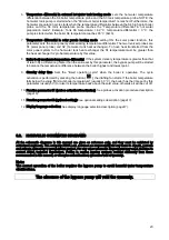
Page 21: ... electronic control starts the hot water tank preparation cycle which will end when the S3 temperature reaches its set value Maximum tank temperature To change the heat exchanging priority the boiler operation must be changed to manual mode with the button A M on the display will appear MAN after that pushing the arrow button the heat exchanging priority passes from hot sanitary water to heating s...

Page 22: ...4 C the manual reset security thermostat opens the supply circuit to the fan stopping it until it will be rearmed NOTE if the boiler temperature often reaches the maximum allowed value control that the air suction port gravitational closing disc is closed when the boiler reaches the working boiler temperature or check for bad door closing or damaged door gaskets 3 Minimum external tank temperature...

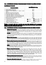
Page 23: ...ss pump will be started to balance the temperature difference between the boiler highest and lowest point 9 Standby delay time Sets the timed operation cycle when the boiler is operative The cycle activation is performed by pressing the button the drafting fan starts If the boiler temperature falls below the value Minimum boiler temperature usually 60 C the boiler has the time set by this paramete...

Page 24: ...emperature probe IR Heating system S5 Heating system return temperature probe V Non return valve 9 3 2 GENERAL CONNECTION DIAGRAM FOR A BOILER WITH SOLAR PANELS AND CLOSED EXPANSION TANK Key PI System pump S1 Solar panel system probe PR Bypass pump S2 Hot water tank probe low point PB Hot water tank circuit pump S3 Hot water tank probe high point PS Solar panel system pump S4 Heating system delive...

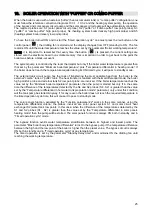
Page 25: ...to the external combo tank or puffer tank The heat transfer is realized with thermal differential mode the boiler high point S4 probe and external tank S2 low point probe are involved If the boiler temperature reaches the value set by the Minimum boiler temperature parameter then the pump is started but only if in the same time the difference of the temperatures detected by the S4 and S2 probes S4...

Page 26: ...d value check that the air suction port gravitational closing disc is closed when the boiler reaches the working boiler temperature or for bad door closing or damaged door gaskets 3 Minimum external tank temperature sets the minimum tank temperature under which if the AUT automatic function is set the external tank heating cycle is started then if S3 probe detects a temperature value less than thi...

Page 27: ...eter the bypass pump will be started to balance the temperature difference between the boiler highest and lowest point 9 Standby delay time Sets the timed operation cycle when the boiler is operative The cycle activation is performed by pressing the button the drafting fan starts If the boiler temperature falls below the value Minimum boiler temperature usually 60 C the boiler has the time set by ...

Page 28: ...robe high point PS Solar panel system pump S4 Heating system delivery temperature probe IR Heating system S5 Heating system return temperature probe V Non return valve SP Plate heat exchanger Key Key PI System pump PR Bypass pump PB External tank circuit pump Puffer or combo Puffer PS Solar panel system pump IR Heating system V Non return valve S1 Solar panel system probe S2 Puffer low point probe...

Page 29: ...ment is in touch with the lower door c The heating circuit must be filled with water and adequately bled from air d The closing valves must be opened if any and the pumps must not be blocked 12 1 FIRING Close the lower door then turn on the main switch 1 Put on the central part of the wood collecting chamber bottom cement plate on the cast iron grate some dry and thin pieces of wood in a crossed p...

Page 30: ...at are too long usually do not fall in an even way they tend to prevent other wood logs over them from falling down Open the wood chamber door slowly to avoid releasing smoke outside During the operation of the boiler the lower door must not be opened under any circumstance Avoid especially in the middle seasons excessive fuel loading so as not to have the boiler in standby mode for a long time an...

Page 31: ...wnward it is mandatory to use less wet wood and or to reduce the overall quantity of fuel loaded The condensation on the wood chamber walls internal surface causes quick corrosion This is not covered by any warranty being caused by incorrect boiler use wet wood excessive loading etc The smoke circulating in the flue passages will be rich in steam content using wet wood When the smoke comes in touc...

Page 32: ...c how long they will last depends as well upon the flame acidity degree more or less accurate cleaning and maintenance of the whole grate zone if the boiler operates correctly within the standard parameters or not They are excluded from the warranty covering and must be considered from any point of view expendable materials The same considerations apply to the catalyst elements and the drafting fa...

Page 33: ... its thermal power and especially the humidity degree and the average ash dimensions employing a grate with different slot shape may be required in order to prevent slots from plugging Usually the two longitudinally or transversely slotted grates do not feature visible differences in the output power The transversely slotted grate pic 5 and pic 6 is better suited when using very dry wood with high...

Page 34: ...ormal value This is not an error because a disabled probe always shows The boiler temperature does not rise and the display shows door open Check for a correct ajar switch connection as shown on the electrical schematic diagram If the message is still shown check for correct microswitch positioning with the door closed if necessary adjust the microswitch position The reading of one or more probes ...

Page 35: ...er tends to cut off leaving an incurved wood mass unburnt in the wood chamber The restart is abnormally long with a difficulty flame formation a The grate is plugged b Not enough primary air a Unplug the grate slots b Increase the primary air The flame is noisy and a lot of white and black ash is produced The boiler features high fuel consumption a Too much primary air a Decrease the primary air T...

Page 36: ...open heating system pump or bypass pump stuck or blocked faulty electronic board Another tip if a greater working temperature is required than the preset value of 80 C increase the parameter 3 Maximum temperature in thermal inertial mode 16 GENERAL TECHNICAL TIPS 16 1 SETTINGS AND HIGHEST PERMITTED TEMPERATURES High power boilers are often used to heat industrial plants in the wood processing sect...

Page 37: ...OSIONS Under poor flue draft conditions and using very dry wood filling completely the wood loading chamber gases released by the wood may accumulate in the chamber When the fan is started again the compound air released gases may fire causing explosions in the wood chamber Anyway this will not harm the boiler because of the presence of antideflagration doors in the back part of the boiler 17 MODE...

Page 38: ...VA IT 01588670206 Tel 0376 372206 Fax 0376 374646 E mail arca arcacaldaie com Tlx 301081 EXPMN I Direzione Commerciale Tel 0376 372617 Gestione Ordini Clienti Tel 0376 371454 Ufficio Tecnico Tel 0376 371454 Produzione caldaie a gas Via Papa Giovanni XXIII 105 20070 San Rocco al Porto Lodi Tel 0377 569677 Fax 0377 569456 ...

Reviews: