background image


7


PRK 1520 

PRK 1870 

PRK 2350 

PRK 3000 

PRK 3500 

 kW 
 

kcal/h x 1000 

1.180 ÷ 1.520 

1.014,8 ÷ 1.307,2 

1.480 ÷ 1.870 

1.278,8 ÷ 1.608,2 

1.830 ÷ 2.350 

1.573,8 ÷ 2.021 

2.450 ÷ 3.000 
2.107 ÷ 2.580 

2.780 ÷ 3.500 

2.390,8 ÷ 3.010 

 kW 
 

kcal/h x 1000 

1.270 ÷ 1.664 

1.092,9 ÷ 1.431 

1590 ÷ 2045 

1.367,4 ÷ 1.758,7 

1.980 ÷ 2.572 

1.702,8 ÷ 2.211,9 

2.642 ÷ 3.285 

2.272,1 ÷ 2.825,1 

3.015 ÷ 3.835 

2.592,9 ÷ 3.298,1 

Combustion chamber volume 

m³ 

1,55 

1,94 

2,577 

3,033 

3,636 

 kW/m³ 
 kcal/h 

m³ 

1.073,5 

923.210 

1.050 

903.086 

998 

858.280 

1.083 

931.454 

1.054,7 

907.068 

Exchange surface 

m² 

33,1 

41,2 

49,5 

57,8 

71,1 

 kW/m² 
 kcal/h 

m² 

45,9 

39.492 

45,4 

39.034 

47,5 

40.828 

51,9 

44.637 

49,2 

42.335 

Smoke 

duct 

number 

n° 

61 69 79 99 128 

Smoke duct diameter 

Ø est. 

1½” 

1½” 

1½” 

1½” 

1½” 

Boiler 

weight 

kg 

2.610 3.220 4.010 6.030 7.240 

Water content                                                                        lt. 

1.650 

2.080 

2.690 

3.740 

4.490 

Operating pressure 

bar 

Hydraulic pressure 

bar 

Max. 

operatine 

temperature 

°C 

95 95 95 95 95 

Water loss of heat 

t=15°C mbar 

43 46 40 58 40 

Combustion chamber pressure 

mbar 

5,8 

6,5 

6,8 

Minimum efficiency  at 100% 

89,2 

89,2 

89,2 

89,2 

89,2 

Efficiency at 100% 

91,35 

91,4 

91,5 

91,4 

91,3 

Minimum effciency at 30% 

87,8 

87,8 

87,8 

87,8 

87,8 

Efficiency at  30% 

92,8 

92,9 

92,9 

92,5 

93,2 

Loss of heat at the chimney with working burner 

8,22 

8,2 

8,12 

8,21 

8,29 

Loss of heat at the chimney with burner out 

0,17 

0,20 

0,18 

0,2 

0,16 

Loss of heat at the jacket  

t=50°C % 

0,43 0,4 0,38 0,39 0,41 

Burner connection (Ø) 

mm 

320 

370 

370 

370 

370 

Flue connection (Ø) 

mm 

450 

500 

550 

600 

700 

Min. 

chimney 

depression 

mbar 

0,2 0,2 0,2 0,2 0,2 

Max smoke temperature 

°C 

197 

188 

193 

188 

195 

Smoke temperature in the output range 

°C 

147 ÷ 197 

149 ÷ 188 

159 ÷ 193 

152 ÷ 188 

155 ÷ 195 

CO

2

 a gas 

10,2 

9,8 

10,4 

10,2 

9,9 

CO 

gas 

ppm 

69 55 70 77 68 

NOx 

gas 

ppm 

71 52 72 74 73 

Max. light oil smoke flow rate 

m³/h 

3.928 

4.828 

6.276 

8.016 

9.358 

Max. methane smoke flow rate 

m³/h 

3.490 

4.289 

5.691 

7.269 

8.486 

Light oil burning air  volume (practice)  m³/h 

2.146 2.638 3.311 4.229 4.937 

Methane burning air  volume  (practice) 

m³/h 

1.989 

2.445 

2.949 

3.766 

4.397 

Combustion chamber dimensions (DiameterxLenght) 

mm 

880 

×

 2.550 

944 

×

 2.760 

1.020 

×

 2.780 

1.211 

×

 2.720 

1.211 

×

 3.000 

Thermostat adjustment range 

°C 

55 ÷ 80 

55 ÷ 80 

55 ÷ 80 

55 ÷ 80 

55 ÷ 80 


Output 

Fornace output 


Thermal load 

Thermal output 

Summary of Contents for MK 100

Page 1: ...MK PRK Installation Usage Maintenance ...

Page 2: ......

Page 3: ...4 1 MINIMAL VALUE OF THE BURNER OUTPUT AT FIRST STAGE 12 5 INSTALLATION 12 5 1 HYDRAULIC DIAGRAM 12 5 2 JACKET MOUNTING 13 5 3 ANTICONDENSATION PUMP 15 5 4 FLUE 15 6 USAGE 15 6 1 FIRST IGNITION CONTROL 15 6 2 RUNNING DATA 15 6 3 REDUCED OUTPUT RUNNING 16 6 4 BOILER WATER TEMPERATURE 16 6 5 SYSTEM IGNITION 16 6 6 BOILER THERMOSTAT SET VALUES 16 6 7 BOILER WATER 17 7 MAINTENANCE 18 7 1 EVERYDAY MAIN...

Page 4: ......

Page 5: ...not let children play with it Before doing every kind of maintenance or cleaning operation disconnect the boiler from its electric supply working on the installation switch In case of boiler damage or malfunctioning make inactive the boiler and do not try to repair it Call the post sale authorised centre Use only original spare parts The non observance of the above mentioned notices could seriousl...

Page 6: ... 7 2 7 2 7 4 3 4 3 kW m kcal h m 20 3 17 423 25 3 21 787 29 7 25 513 21 0 18 060 23 3 20 020 Smoke duct number n 18 18 18 23 23 Smoke duct diameter Ø est 1 1 1 1 1 Boiler weight kg 200 220 220 300 310 Water content l 90 90 90 140 140 Operating pressure bar 5 5 5 5 5 Hydraulic pressure bar 7 5 7 5 7 5 7 5 7 5 Max operating temperature C 95 95 95 95 95 Water loss of heat t 15 C mbar 8 10 13 12 14 Co...

Page 7: ...2 Min efficiency at 100 88 2 88 3 88 5 88 7 88 8 Efficiency at 100 91 6 91 3 91 3 91 8 91 0 Min efficiency at 30 86 3 86 5 86 8 87 1 87 2 Efficiency at 30 92 8 92 5 92 6 93 92 0 Loss of heat at the chimney with operating burner 7 27 7 66 7 58 7 18 7 84 Loss of heat at the chimney with burner out 0 25 0 29 0 22 0 24 0 26 Jacket losses t 50 C 1 13 1 04 1 12 1 02 0 96 Burner connection Ø mm 150 150 1...

Page 8: ...95 710 1 200 120 70 670 790 1020 110 640 310 500 595 710 1 200 120 80 670 790 1020 110 640 310 500 595 710 1 200 120 90 730 890 1210 110 720 310 580 660 890 2 200 150 100 730 890 1210 110 720 310 580 660 890 2 200 150 120 730 890 1210 110 720 310 580 660 890 2 200 150 140 730 890 1390 110 720 310 580 660 1070 2 200 150 170 730 890 1390 110 720 310 580 660 1070 2 200 150 230 850 1010 1430 135 380 6...

Page 9: ...259 040 1 400 4 1 204 344 Exchange surface m 8 3 9 3 9 7 9 7 12 kW m kcal h m 42 36 120 45 38 700 48 5 41 710 54 46 440 50 43 000 Smoke duct number n 28 30 33 33 33 Smoke duct diameter Ø est 1 1 1 1 1 Boiler weight kg 650 740 1 070 1 070 1 250 Water content lt 340 400 470 470 570 Operating pressure bar 6 6 6 6 6 Hydraulic pressure bar 9 9 9 9 9 Max operatine temperature C 95 95 95 95 95 Water loss...

Page 10: ... 89 2 89 2 89 2 89 2 Efficiency at 100 91 9 91 5 91 7 91 25 91 3 Minimum effciency at 30 87 8 87 8 87 8 87 8 87 8 Efficiency at 30 93 9 92 2 93 2 92 9 93 2 Loss of heat at the chimney with working burner 7 65 8 7 78 8 17 8 22 Loss of heat at the chimney with burner out 0 18 0 21 0 18 0 20 0 18 Loss of heat at the jacket t 50 C 0 45 0 5 0 52 0 58 0 48 Burner connection Ø mm 240 240 305 305 305 Flue...

Page 11: ...cy at 100 89 2 89 2 89 2 89 2 89 2 Efficiency at 100 91 35 91 4 91 5 91 4 91 3 Minimum effciency at 30 87 8 87 8 87 8 87 8 87 8 Efficiency at 30 92 8 92 9 92 9 92 5 93 2 Loss of heat at the chimney with working burner 8 22 8 2 8 12 8 21 8 29 Loss of heat at the chimney with burner out 0 17 0 20 0 18 0 2 0 16 Loss of heat at the jacket t 50 C 0 43 0 4 0 38 0 39 0 41 Burner connection Ø mm 320 370 3...

Page 12: ...410 1410 1780 1660 1910 1960 1960 2360 2765 3005 3005 2965 3280 G mm 640 640 720 720 720 760 760 850 850 850 900 900 900 920 900 H mm 540 680 450 450 800 620 870 1125 1125 1450 1830 2030 1230 1200 1320 M mm 835 975 770 770 1120 970 1220 575 575 750 950 1015 1722 1780 1900 N mm 500 500 650 650 650 700 700 750 750 750 830 900 970 1095 1095 R mm 790 790 850 850 850 920 920 790 790 790 800 900 970 109...

Page 13: ... light system pump 16 Anti inertia thermostat inside 8 Boiler adjustment thermostat 3 2 WIRING DIAGRAM IG General switch TIT Anti inertia thermostat IP System pump switch PI PI System pump IB Burner switch S Light in IG included TS Safety thermostat S2 Running light PI TR Boiler adjustment thermostat S3 Burner block out light TM Min temperature thermostat B4 Hour meter TA Room thermostat ...

Page 14: ...ivered and connected by the installer 3 5 RUNNING Bring all the switches to the position 1 adjust the set point boiler temperature by means of the TR thermostat position number 8 on the switchboard The PI system pumps starts running when the boiler reaches the minimal temperature The red light on the switchboard number 5 position will shine The possible room thermostat is to be connected to the te...

Page 15: ...140 170 170 MK 220 280 200 PRK 320 400 220 PRK 500 600 740 830 260 PRK 1050 1200 300 PRK 1450 350 PRK 1850 2350 400 PRK 3000 3500 450 Blast tubes are to be wrapped with a glass fibre or mineral wool insulation in order to avoid burner plate overheating and furnace heat losses Important Even if the burner is delivered by ARCA it has not the same warranty as the boiler Its warranty depends on the co...

Page 16: ...20 106 000 123 MK 280 132 000 153 PRK 320 160 000 186 PRK 400 225 000 262 PRK 500 275 000 320 PRK 600 335 000 390 PRK 740 412 000 480 PRK 830 464 000 540 PRK 1050 568 000 660 PRK 1200 653 000 760 PRK 1450 790 000 920 PRK 1850 1 005 000 1170 PRK 2350 1 280 000 1490 PRK 3000 1 548 000 1800 PRK 3500 1 800 000 2100 5 INSTALLATION 5 1 HYDRAULIC DIAGRAM Legend C Boiler PA Anti condensation pump P Air bl...

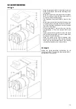
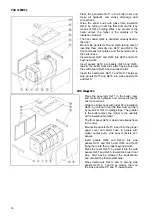
Page 17: ...f 7 and Ref 8 the front and back duct plates and the bended part in the boiler base Fix the panel Ref 11 just over the door into the bayonet joints of the side panels Ref 5 and Ref 6 Insert panels Ref 9 and Ref 10 into the back part of side panels Ref 5 and Ref 6 place them by means of a light pressure Place the upper cover Ref 13 between side panels Ref 5 and Ref 6 after having screwed them into ...

Page 18: ...e panels Ref 5 and Ref 6 into side panel Ref 8 and Ref 9 PRK 830 3500 Place the generator Ref 1 in the boiler room and make all hydraulic and smoke discharge duct connections Wrap the boiler body with glass fibre insulation Ref 2 by cutting it near the flow duct and fix it by means of Ref 3 holding strips The greater is the boiler output the higher is the quantity of the insulation material The fr...

Page 19: ... out of the boiler and burner connection Control the flue draught when the system is operating control the flue depression Control the expansion vessel water level The water level must respect foreseen levels If steady water adding are required search for their cause i e water losses insufficient expansion vessel volume etc A steady water change can result in an easier boiler corrosion and calcare...

Page 20: ...er represents the better way to do it because it allows a high boiler temperature even when the heating system water temperature is low In this way you have a good protection against corrosion and the boiler will run longer The return water has never to be lower than 45 C using gas light or heavy oil with a sulphur percentage lower than 1 50 C using heavy oil with a sulphur percentage higher than ...

Page 21: ...tal salinity 3000 p p m Total alkalinity in French degree TA 75 French Silica S O i 2 150 p p m Phosphates P O 2 5 30 p p m pH 9 5 Even few millimetre thick incrustations result in sheet overheating because of their low thermal conductivity As a consequence there can be metal expansions localized thermal changes and welding damages Heating system water treatment is necessary in case of very wide s...

Page 22: ...ely brush and scrape if necessary the furnace in order to remove deposits of sulphur and acid substances If there are carbon deposits on furnace walls control nozzles and the burner combustion head adjustment After the above described operations carry out a combustion analysis as required by present regulations 7 2 SEASONAL MAINTENANCE OPERATIONS Both the boiler and the system must be kept full of...

Page 23: ...use steel sheet overheating a periodic scaling is necessary In case of a steady scaling do not use a corrosive product After the first heating season carefully scale the boiler In case of steady running scale the boiler 5 months after the first starting up Then every 2 3 years depending on system specifications Periodically remove boiler mud For all these operations call a specialized centre 7 5 P...

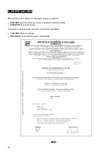
Page 24: ...European regulations 92 42 CEE about the efficiency of gas or liquefied combustion boilers 90 396 CEE about gas devices The electrical devices satisfy the following European regulations 73 23 CEE about low voltage 89 336 CEE about electromagnetic compatibility MK ...

Page 25: ...21 PRK ...

Page 26: ...tion Via 1 Maggio 16 46030 San Giorgio Mantova I P IVA IT 01588670206 Tel 39 0376 372206 Fax 39 0376 374646 E mail arca arcacaldaie com Wall hung boilers production Via Papa Giovanni XXIII 105 20070 San Rocco al Porto Lodi Tel 39 0377 569677 Fax 39 0377 569456 ...

Reviews: