SET-UP AND SAFE OPERATING PROCEDURES
7-21
89210000
SECTION 7:
OPERATING THE N6000 SYSTEM
Find out whether you will use a constant current (CC) or constant potential (CP) power source.
The Controller must be properly set to match the power source.
CHANGING MODE OF OPERATION (CC OR CP)
To change the mode of operation do these things:
WARNING
DISCONNECT ALL POWER!
1. Lift the plastic cover on the Controller. Remove the three top screws on the face of
the front panel holding the plastic cover. Remove the remaining seven screws around
the front panel. (Support the panel so it won’t fall free). Carefully move the panel
aside to expose the interior of the Controller. (Do not disconnect wires.)
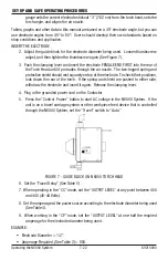
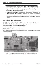
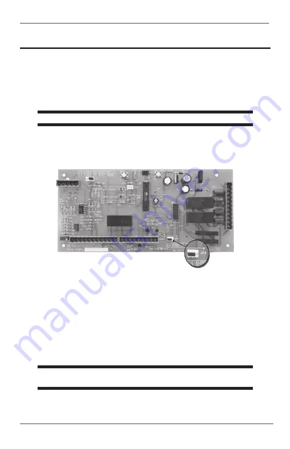
FIGURE 6 - MASTER CONTROL CIRCUIT BOARD “CC” & “CP” JUMPER
2. On the back wall of the Controller is the circuit board. On the bottom edge locate the
CC/CP jumper. Place the control in the correct mode by moving the jumper left or
right as printed on the circuit board. Later, a front panel indicator will confirm your
setting.
3. Replace the front panel and replace the screws.
STARTING CONDITIONS “CC” AND “CP” MODE
WARNING
Do not turn on DC power or compressed air until you are ready to begin
gouging.
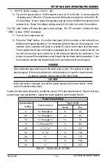
1. Place the Torch Head above the workpiece you want to start gouging. Using the Angle
Gauge supplied with the N6000, adjust the torch head to the workpiece. The angle
Jumper installed on pins 1-2 = CC Mode
Jumper installed on pins 2-3 = CP Mode
Operating the N6000 System


