7-22
SET-UP AND SAFE OPERATING PROCEDURES
89210000
gauge sets the correct electrode stickout “3” (7.62 cm) from the torch head, sets the
torch angle, and aligns the air nozzle.
Tables, graphs and other data in this manual are based on a 45° electrode angle, but you can
use electrode angles from 45° to 60°. Users should develop their own standards based on
shop conditions and application.
INSERT THE ELECTRODE
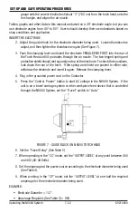
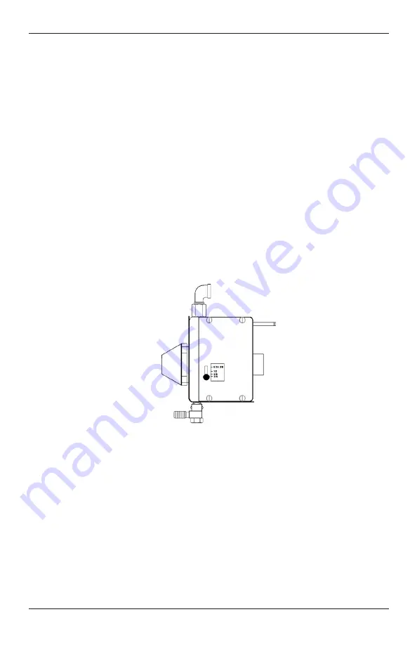
2. Adjust the guide block for the electrode diameter being used. Loosen thumbscrew,
adjust, and then tighten the thumbscrew again (See Figure 7).
3. Push the clamping lever and insert the electrode FEMALE END FIRST into the rear of
the Torch Head until it protrudes through the air nozzle. The two-legged spring and
protective shield should rest squarely on top of the electrode. To check their positions,
look down the rear of the torch. If the spring and shield are pushed to either side,
withdraw the electrode and insert it again. Release the clamping lever.
4. Plug in the grounded power cord on the Contactor.
5. Press the “Control Power” button to start AC voltage in the N6000 System. If the
unit is on a travel carriage system or other workpiece feed device that is controlled
through the N6000 System, set the “Travel” switch to “Auto.”
FIGURE 7 - GUIDE BLOCK ON N6000 TORCH HEAD
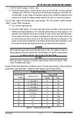
6. Set the “Travel Delay” (See Table 5).
7. When operating in the “CC” mode, set the “OUTPUT LEVEL” at any point between 400
and 440 (40-44 Volts).
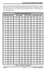
8. Set the amperage at the power source according to the electrode diameter being used
(See Table 4).
9. When working in the “CP” mode, set the “OUTPUT LEVEL” at one-half the required
amperage for the electrode diameter being used.
EXAMPLE:
• Electrode Diameter = 1/2”.
• Amperage Required, (See Table 2) = 850.
Operating the N6000 System


