background image

 24 


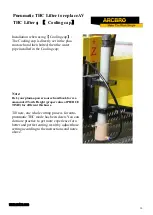
Pneumatic THC Co

-

assembling


1

-

 Connect the 

air compressor 

to the Pneumatic TCH connector; 

the  pressure can be 0.3

-

 0.5 kpa.


2


Mount the Pneumatic THC Lifter to replace AV THC Lifter and 

keep the red IHS wire

s tip away from any conductive stuff. 


3


Mount the torch and load the water cooling tip with the hose. 

And use hose clamps


4


Connect the water pump to supply water to the water cooling tip.


Thin Sheet Cutting Practice


Pneumatic THC Lifter to replace 
AV THC Lifter 

;【

PLATEN


1

-

Remove the anti

-

collision input cable.


2


Remove the lifter motor control cable.


3


Remove the cover of the lifter, and then remove the 

lifter


4


Keep the red IHS wire

s tip away from any conduc-

tive stuff. 


Summary of Contents for Stinger 1010

Page 1: ...utting Machine User s Manual Reference AM Revision 3 Date of issue May 22nd 2017 Beijing ARCBRO LTD Xinfang Industrial Park NO 218 ChaoYang District 100024 Beijing China Tel 86 10 65798995 Fax 86 10 6...

Page 2: ...may be reproduced stored in a retrieval system or transmitted in any form or by any means electronically mechanically by photocopy recording or otherwise without the prior written permission of ARCBRO...

Page 3: ...received the machine Whenever you have any questions during the process of assembling or operating please feel free to contact us via Call Email or Online help 7x24 May you enjoy a wonderful CNC cutt...

Page 4: ...color LCD screen Internal library 24 kinds of shape External format TXT or NC format Language English Chinese Spanish Russian French Japanese Czech and Slovenia Temperature 1 40 34 104 Notes Note 1 N...

Page 5: ...ing high accurate drawing or any shape profiling can be achieved efficiently by Stinger 1 2 Application Stinger is an ideal CNC Plate Cutting Machine widely used in industry field such as shipbuilding...

Page 6: ...neutral connection and insulation of the torch handle Then isolate the workbench from the ground or install no load open circuit relay in the electrical control system 4 The cutting operator and assis...

Page 7: ...e of damage or opened please take clear photos on file Then contact the transport company and ARCBRO technical sup port department Do not sign when situation above happened try to contact ARCBRO techn...

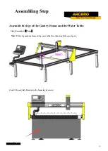
Page 8: ...8 Mechanical Assembling Steps...

Page 9: ...nd the drag chain with cables Step 3 Connect and fix all legs onto the Water Table each leg fixed by 2 bolts Step 4 Connect and fix all legs onto the Gantry Frame by top screw M16 Hold the top screw f...

Page 10: ...Assemble the legs of the Gantry Frame and the Water Table Step 5 Assemble Beam Note Pls fix the machine frame on the water table first then install the cross beam Step 5 Fix each Side Board onto the f...

Page 11: ...ard onto the frame leg by screws Step 8 Adjust the Level Bolts according to the measurement of Level Gauge to make sure a the Water Table level b the 2 track on same horizontal level The level precisi...

Page 12: ...y Power Supply cable Ground wire to cutting plate ARC START cable to plug of the plasma power source DIV ARC cable to Original Arc Voltage ports inside of the plasma power source Note Ref your plasma...

Page 13: ...sure to keep the THC Lifter of Stinger on the proper position Torch loading Step 12 Load the plasma torch to the holder IHS wire Connection Step 13 Connect the IHS wire to the shield of the plasma tor...

Page 14: ...F7 function key Red button 0 Stop running shift up selection blank S torch up line feed enter key S torch down F manual speed to the top of the line PIERCE Arc flame generating button END F manual sp...

Page 15: ...15 Parameter Set for Thick Plate Cut Arc Voltage THC mode...

Page 16: ...ange it randomly b Then press F7 to save this set Note 1 Row 8th and Row 9th can be adjusted according to different thickness of plate 2 Row 8th for the necessary time of piercing process 3 Row 9th fo...

Page 17: ...17 CONTROL interface set Auto Plasma Cut Mode a Press F5 to enter CONTROL interface b Then press F7 to save this set Note DO NOT change it randomly...

Page 18: ...ch manually to the reference point red cross on shape file Press F6 to Clear the X Y axis Coordinates displaying in bottom left area h Press F1 back to AUTO interface Press F to input a proper cutting...

Page 19: ...urn the screw of the ARCVOLTAGE to adjust the torch height 3 Usually 120 is the proper value of SET ARCVOLTAGE for 3 5mm thickness of carbon steel Ref your plasma power source handbook for recommended...

Page 20: ...ess Enter but ton d Press F2 LOAD F3 SAVE Now the file in USB flash drive is loaded and saved to the system storage for any time usage Load the txt file for Auto cut e Go EDIT interface press F2 LOAD...

Page 21: ...21 Parameter Set for Thin Sheet Cut Pneumatic THC mode 1 Installation of pneumatic device 2 System data setting...

Page 22: ...a Press F4 to enter CONTROL interface b Set the 1st Row 1 We define Plasma mode in system as the pneumatic mode for thin sheet cut c Then press F7 to save this set Note DO NOT change it randomly Go t...

Page 23: ...an be adjusted according to different thickness of plate 2 Row 8th for the necessary time of piercing process 3 Row 9th for the necessary time of first piercing process The torch is cold at the begin...

Page 24: ...stuff 3 Mount the torch and load the water cooling tip with the hose And use hose clamps 4 Connect the water pump to supply water to the water cooling tip Thin Sheet Cutting Practice Pneumatic THC Lif...

Page 25: ...igned with the plasma cap 7 Install the plasma torch and adjust the height of the torch height range 0 5 1mm Switch into manual mode Press CUTOXY the torch goes down adjust the torch height tighten th...

Page 26: ...ode has been down You can do more practice to get more experience for a better and perfect cutting result by adjust those setting according to the instructions and notes above Pneumatic THC Lifter to...

Page 27: ...software install files and the video about how to do the installation Install the software on computer it supports WINDOWS XP WIN7 WIN8 WIN3 3 and WIN10 version Installation steps 1 Read install CD i...

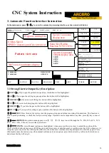
Page 28: ...g and manual adjusting the position of the cutting tool F2 MAN Enter the screen for the manual processing F3 EDIT Edit modify input output the processing program F4 SETUP Set the system parameter F5 D...

Page 29: ...ress Enter G CONTIN select Manual continuous highlighted when you press the arrow keys to adjust the position of the torch click the button to turn on or off When you need two axes move simultaneously...

Page 30: ...rmsandtimedelay 3 2 4 Input and output Below the heavy current switches there are 3 rows 8 indicators The top indicators show the status of 13 input ports indicating no signal input and indicating sig...

Page 31: ...plate This operation can be paused at any moment or cancelled by pressing X key one more times 3 2 11 Y AU SPD Since the manual speed and automatic speed is separate in the system this key is used to...

Page 32: ...compensating width if no necessary to compensate usually in blanking simply enter 0 3 3 6 F6 ASSI This key is used to enter the next lower level of menu as shown in Fig 3 3 below 3 3 7 F3 ROTATE steel...

Page 33: ...system will reminder user to input scale if this key is pressed When the machining program is executed the work size will magnify or minify as per this scale This feature is very useful in cutting gra...

Page 34: ...Input Ports for details If emergency stop is validated all the movement will stop and no output will go on It is used for emergency case 3 5 2 Adjustment of cutting position 3 5 2 1Situations necessar...

Page 35: ...to cut through in machining oper ation handle it in the following ways 3 6 1Return along original path Press PAUSE key to suspend the running system A pause mark will appear on the system display in a...

Page 36: ...is found and wait for subsequent command User may select piercing directly or position adjustment of cutting torch Refer to 3 4 for details If the position of cutting torch does change and is off fro...

Page 37: ...pattern first and then drawa large cross cursor at the piercing point Operator may press S key to zoom in the pattern and observe if it is the expected piercing position If not satisfied operator may...

Page 38: ...press and or keyto move the cutting torch to the edge ofsteel plate in the meantime the speed multiply ingfactorisadjustedto5 automatically Thesystemispreheated Press START key at the end of preheat T...

Page 39: ...H UP TORCH DN GAS HOTUP X TEST Y AU SPEED 1 200MIN 2 200MOUT F ADSPED G CONTINUE PROPORT 1 0 INPUT OUTP UT X 00000 000 WORK MODE Y 00000 000 OPERATE ANGLE 0 00 BEG ORW 0 00 DISTANCE 0 00 CUTLENGTH CRA...

Page 40: ...2 F1 AUTO The system is switched to automatic mode 4 1 3 F2 MOVE If MOVE function highlighted is selected the system will prompt to input MOVE INCREMENT 0050 000 previous input value by default In MOV...

Page 41: ...rogram will be loaded into program editing area if ESC key is pressed the load function will be abandoned 5 1 3 F3 SAVE To save program After a program is edited and ready to save the system will prom...

Page 42: ...CNC cutting operation each step is taken according to a program Each machining program is composed of several command segments each command segment is composed of several function words and each func...

Page 43: ...chiningoriginpoint referencepoint atthe verybeginning Format G92 Xn Yn IfG92isnotfollowedwithX Ycoordinatevalues thenthecurrentX Ycoordinatewillbetakenasreferencepoint Generally whentheorigin pointofm...

Page 44: ...g torch will move along a straight line from the origin point to the end point at the speed of the maximum speed limit multiplied by multiplying factor G00 movement is subject to speed multiplying fac...

Page 45: ...mple G04 L2 4 To delay 2 4 seconds In the execution process of G04 command if START key is pressed the time delay will be disabled and the subse quent program will be executed continually If Exit key...

Page 46: ...e position of cutting torch is corrected Behind G40 the end mark of cutter compensation a G00 command is necessary to adjust the position back 6 4 M Auxiliary Commands M00 Program suspension command T...

Page 47: ...n the subsequent program M08 fixed loop of cutting stop The operation sequence of M08 in flame cutting operation is as follows 1 Close the cutting oxygen valve M13 2 Turn off the height controller M39...

Page 48: ...he piercing torch refer to 7 3 for flame parameter and turn off the torch lowering switch M17 M75 Time delay of torch positioning When positioning the plasma gun lower the torch M16 It will not stop u...

Page 49: ...nFig 7 2 Speedparametersinclude Startingspeed Thestartingand stopspeedofsysteminXaxisand Yaxisinmm minorinch min RefertoControlParametersformore Adjustmenttime Thetimerequiredforthesystemtoacceleratef...

Page 50: ...tance Simplifytheaboveformulatoafractioninlowestterms E g assumetheelectronicgearratiois8 1andthetheoreticaltraveldistanceis2000mmandtheactualtraveldistanceis2651mm 8X 2651 2651 Mechanicalorigin Aspec...

Page 51: ...uttingtorch ThetimedelaywhenM70commandisexecutedinsecond Referto6 4forMauxiliarycommands Loweringdelayofcuttingtorch The time delay when M71 command is executed in second Refer to 6 4 for M auxiliary...

Page 52: ...cuttingprocess Generally arcvoltagetestisdisabledforthinsheetmachining Positioningtestoption InexecutionofM07command itisusedtodeterminetorchpositioningoperationornot Iftheoptionistaken1 torch positi...

Page 53: ...rEnglishsystem whichwillhave parameters displayandcoordinatesexpressedinEnglishunit inch thoughitsupportsmachiningprograminmetricprogram G21 Attention Pleasebecautioustomakeanychangeifnoideaofthespeci...

Page 54: ...F4 Layout The system will prompt user to provide Row number Row number of machined parts array Column number Column number of machined parts array Row pitch Distance between rows Column pitch Horizont...

Page 55: ...put port 9 2 Output Check Move cursor to any position of the 8 optical isolation output ports and change the level state of output with 0 and 1 1 stands for enable while 0 stands for disable Refer to...

Page 56: ...successful the system will prompt Upgraded Successfully and sound one beep If program upgrading fails the system will prompt Upgrade Failure and sound continuous beeps 4 New program startup Power the...

Reviews: