background image

31-DVI33N

 14 


CONVERT THE GAS CONTROL VALVE, MAIN CONTROL MODULE  AND REMOTE 
 

GAS CONTROL VALVE: 

 
Unscrew the threaded regulator cap on the control valve. 
 
Press down on pressure regulator tube and rotate 90 degrees.  The tube should only come up half way for 
LP after released and the line should point to LP.  Screw cap back on. 
 
Remove Low limit screw (brass screw in front and to the right of the valve motor) and replace with the 
new screw supplied in the conversion kit. 


MAIN CONTROL MODULE: 

 
Press and hold the learn button on the main control module for 20 seconds (on top next to the cable con-
nection).  A beep (1 second for LP and 3 seconds for natural gas) will be heard letting you know the pro-
cedure has been completed. 
 

REMOTE: 
 

Press and hold the Flame Rear and Prog/Time buttons on the remote simultaneously for 5 seconds.  The 
Temperature will start to flash.  Push the set button until the NG or LP on the lower left of the display is 
flashing.  Push the up or down button until the proper fuel type is displayed.  Wait 20 seconds and the dis-
play will stop flashing and the remote is now set for the desired fuel type.


COMPLETE THE CONVERSION 
 

Turn on the gas and electrical supplies.  
 
Turn on the fireplace so the burner is on  
 
Check for leaks at 

all

 connections. 

 
Test inlet pressure.  Visually check pilot flame.  Flame should envelope top of the flame sensor and extend for-
ward onto the burner.  To adjust pilot turn the pilot adjustment screw on the control valve clockwise to decrease 
or counter clockwise to increase pilot flame. 
 
Turn fireplace off 
 
Affix gas type label to the rating plate label.  (Bottom right side, under the door  frame of insert on pull  chain) 
 
Complete the conversion label and affix to valve assembly plate. 


CONVERSION KIT INSTRUCTIONS CONT. 

Summary of Contents for 31-DVI33N

Page 1: ...instructions If you cannot reach your gas supplier call the fire department Installation and service must be performed by a qualified installer service agency or the gas supplier This appliance may be installed in an aftermarket permanently located manufactured home USA only or mobile home where not prohibited by local codes This appliance is only for use with the type of gas indicated on the rati...

Page 2: ......

Page 3: ...less expensive to operate Adjustable Fan Speed Each 31 DVI33N comes complete with a heat activated circulation fan with a fully adjustable speed control Adjustable Flame The flame aesthetics and heat output can be adjusted to suit the owner s liking and heating needs Solid Construction The 31 DVI33N is mainly constructed of 16 and 18 gauge galvanized and aluminized coated steel for long life and d...

Page 4: ... 17 Surround Installation and Rocker Switch Wiring 18 Log Placement 19 24 Final Installation Check and Initial Operation 25 First Fire and Lighting Instructions CAUTION 26 Lighting Instructions on Rating Plate 27 Remote Control Setup and Operation 28 32 Glass Door Removal If Your Glass Should Break 33 Maintenance and Cleaning the Appliance 34 Servicing Under Warranty and Adjusting Primary Air 35 C...

Page 5: ...e and at least annually by a professional service person More frequent cleaning may be required due to excessive lint from carpeting bedding materials etc It is imperative that the control compartments burners and circulating air passageways of the appliance are kept clean Do not use this appliance if any part has been under water Immediately call a qualified service technician to inspect the appl...

Page 6: ...nstallation must conform with the Manufactured Home Construction and Safety Standard Title 24CFR Part 3280 or when such a standard is not applicable the Standard for manufactured Home Installations ANSI NCSBCS A225 1 or Standard for Gas Equipped Recreational vehicles and Mobile Housing CSA Z240 4 SPECIFICATIONS Natural Gas NG Propane LP Manifold Pressure 3 5 in W C 0 9 kPa 10 0 in W C 2 5 kPa Min ...

Page 7: ...31 DVI33N 7 RATING PLATE ...

Page 8: ...llowing different ways They are shipped in the Controls In configu ration They can be moved to the Controls Out configuration by removing the two mounting screw on each side and swinging the panels out and replacing the screws They can also be disconnected and placed remotely within the limits of the gas connections and electrical wiring making sure to place them away from any heat source over 150...

Page 9: ...ilt fireplace has no gas access hole s provided an access hole of 1 1 2 38 1 mm or less may be drilled through the lower sides or bottom of the firebox in a proper workmanship like manner This access hole must be plugged with non combustible insulation after the gas supply line has been installed The fireplace flue damper can be fully blocked open or removed for installation of the gas fireplace i...

Page 10: ...y metal parts is prohibited except the metal floor J as specified The metal floor of the firebox may be removed only if the following is strictly adhered to The metal floor J may be removed to allow additional room for installation of the in sert If the floor is removed the insert must be placed directly on the metal base of the metal fireplace Under no circumstance can it be placed directly on a ...

Page 11: ...antle allowed in shaded area Mantle extension maybe increased 1 25 4 mm for each additional 1 25 4 mm increase in clearance height Example If using a 5 127 mm reduce minimum height to 31 788 mm If using a 4 102 mm reduce minimum height to 30 762 mm 12 305mm Minimum Height From Bottom of Appliance 38 966 mm with a 12 305 mm mantel Note If existing wood fire place hearth protection is removed it mus...

Page 12: ... individual manual shutoff valve during any pressure testing of the gas supply piping system at test pressures equal to or less than 1 2 psig 3 5 kPa Failure to do so will damage the appliance s gas valve Such damage is not covered by the manufacturer s warranty Natural Gas Pressure Settings The inlet supply or line pressure must be a minimum of 4 5 W C 1 2 kPa and a maximum of 14 W C 3 5 kPa The ...

Page 13: ... 49 for LP 32 for Natural Gas 1 gas type label 1 Low limit screw 52 PREPARE THE FIREPLACE Remove the surround glass frame assembly logs and brick if applicable Remove the burner cover by removing the two screws at the back and lifting straight up Remove burner by removing the screw on each side of the burner and sliding the burner to the right until it lifts straight up Remove the burner orifice u...

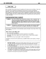
Page 14: ...s on the remote simultaneously for 5 seconds The Temperature will start to flash Push the set button until the NG or LP on the lower left of the display is flashing Push the up or down button until the proper fuel type is displayed Wait 20 seconds and the dis play will stop flashing and the remote is now set for the desired fuel type COMPLETE THE CONVERSION Turn on the gas and electrical supplies ...

Page 15: ...ete with a temperature activated fan and rheostat installed and wired to a three prong grounding plug for your protection against shock hazard and should be plugged in directly into a properly grounded three prong receptacle Do not cut or remove the grounding prong from this plug NOTE This appliance when installed must be electrically grounded in accordance with local codes or in the absence of lo...

Page 16: ...mm Masonry chimneys may take various contours which the flexible liner will accommodate however keep the flexible liner as straight as possible avoiding unnecessary bending but at all times keep a minimum of 3 76 mm inside bend radius The Air Intake Flex Liner must be connected to the inlet air collars of the termination cap and the appli ance The Exhaust Flex Liner must be connected to the exhaus...

Page 17: ...rovided with the unit 8 Install exhaust vent restrictors provided with the unit on Natural Gas appliances only Seal and attach the end of the flex marked Exhaust to the collar marked Exhaust on the appliance 9 Caulk all joints using a high temperature sealant such as milpac DO NOT USE SILICONE SEALANTS Use of silicon sealants voids the warranty of the pilot assembly NOTE The vertical termination c...

Page 18: ...unit into the fireplace and slide the excess flue liner material back onto the chimney Before the ap pliance is fully recessed into the fireplace attach the surround onto the appliance Attach the surround to the appliance at the locations shown by lining up the tabs on the sur round with the slots on the unit Make sure the surround drops down and fully engages Then finish with the wiring connectio...

Page 19: ... Authorized Archgard Dealer Gas and vent connection must be made before installing the embers and logs on the pan burner NOTE Improper placement of logs and embers may cause sooting on the internal parts and glass and will not be covered under warranty Do not use broken or damaged logs Locate the embers and logs and place them on their prospective locations Refer to the pictured instructions on th...

Page 20: ...31 DVI33N 20 Logs LOG 1 LOG 7 LOG 4 LOG 2 LOG 6 LOG 3 LOG 5 ...

Page 21: ...ck shelf and to the left so it is almost touching Log 1 Force the log down onto the locater pins NOTE There are no holes in Log 7 must use gentle force Step 1 Locate Log 1 and align the holes in the bottom line up with the two locater pins Push the top of the log up so it is against the back shelf Push down firmly onto locater pins ...

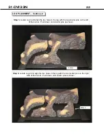
Page 22: ...gn the two holes in the log with the two locater pins on the left of the burner Push down onto locator pins as shown Step 4 Locate Log 2 and align the two holes in the log with the two locater pins on the right side of the burner Push down onto locator pins as shown LOG 2 ...

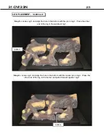
Page 23: ...he hole in the bottom with the pin in log 3 Place the other end of the log in the saddle of log 1 LOG 5 Step 6 Locate Log 6 and align the hole in the bottom with the locater pin in log 4 Place the other end of the log on the burner and pulled forward against log 2 LOG 6 ...

Page 24: ...te Log 4 and align the hole in the bottom with the pin on the burner surround tray Place the other end onto log 2 as shown LOG 4 Black embers Step 8 Place black embers around logs as shown do not block the holes in the burner ...

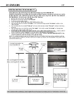
Page 25: ...rder This will include 1 Perform leak tests of supply line gas control valve supply line from gas control valve and pilot assembly 2 Clocking the appliance to ensure the correct firing rate see page 9 of this manual 3 If required adjusting the primary air to burner to ensure that the flame does not carbon or soot 4 Check for proper operation including correct drafting 5 The FAN system should be tu...

Page 26: ...isted directly above or as shown on the front cover of this manual 3 Do not use this appliance if any part has been under water Immediately call a qualified service technician to inspect the appliance and to replace any part of the control system and any gas control which has been under water 4 This appliance is equipped with an ignition device which automatically lights the pilot and main burner ...

Page 27: ...31 DVI33N 27 LIGHTING INSTRUCTIONS ON RATING PLATE ...

Page 28: ...31 DVI33N 28 REMOTE CONTROL SETUP AND OPERATION ...

Page 29: ...31 DVI33N 29 REMOTE CONTROL SETUP AND OPERATION CONT ...

Page 30: ...31 DVI33N 30 REMOTE CONTROL SETUP AND OPERATION CONT ...

Page 31: ...31 DVI33N 31 REMOTE CONTROL SETUP AND OPERATION CONT ...

Page 32: ...31 DVI33N 32 REMOTE CONTROL SETUP AND OPERATION CONT ...

Page 33: ...the door to ensure the door is seated all the way down on the catches 7 Pull the finger rings out and down to engage in the slots on the top of the door frame 8 Push the finger rings back in IF YOUR GLASS BREAKS WARNING Do not operate appliance with the glass front cracked or broken Replacement of the glass should be done by a licensed or qualified service person In the event your glass cracks or ...

Page 34: ... cleaner to clean off any dust or lint After cleaning the logs and embers must be replaced as per the instructions in this manual Once a year have a qualified service technician Completely inspect the appliance and the venting system if the vent pipe or seal is found to be defective replace and or reseal follow the instructions found in the venting instructions section Clean and remove any lint ac...

Page 35: ...tment The right side shows yellow sooty flames requiring increase in shutter opening or cleaning of shutter area due to lint buildup WARNING Servicing of this appliance must be conducted by a qualified service technician Improper servicing adjustment or alteration of this appliance may cause property damage personal injury or loss of life All servicing should be conducted with the appliance cold A...

Page 36: ...at the readings obtained are within specs as shown on the appliance rating plate 6 Be sure to tighten the set screw inside the tap after you have finished taking pressure readings 7 Check for leaks CHECKING INLET AND OUTLET GAS PRESSURE CHECKING AND ADJUSTING PILOT Fig 1 The pilot flame should have the characteristic as shown in the illustration to the right The flame should not have yellow tips b...

Page 37: ...LASS DOOR REMOVAL instructions within this manual 2 Remove the log set Follow LOG PLACEMENT instructions within this manual 3 Remove the pan burner Follow instructions for CHANGING MAIN BURNER ORIFICE within the conversion section of this manual 4 Remove the access cover section set at 45 degree angle of the firebox by removing the 1 4 hex head screws and lifting out When replacing make sure to re...

Page 38: ...31 DVI33N 38 WIRING SCHEMATICS ...

Page 39: ...0 634720 2 Log 2 Right Mid 1 EA 310 634720 3 Log 3 Left Mid 1 EA 310 634720 4 Log 4 Right 1 EA 310 634720 5 Log 5 Left Top 1 EA 310 634720 6 Log 6 Front Crossover 1 EA 310 634720 7 Log 7 Right Rear 1 EA 310 0020 Black Embers 2 cup bag 1 EA LOG 1 LOG 7 LOG 4 LOG 2 LOG 6 LOG 3 LOG 5 ...

Page 40: ... you cannot solve the problem contact your Archgard Dealer or representative When calling for help please have the following information Model of your Fireplace Serial Number Place of Purchase Date of Purchase Problem Description NOTE Warranty may be void if work is carried out by an unqualified person s Only original Archgard parts may be used Please consult your Archgard dealer or representative...

Page 41: ...king cracking or pinging sound when my fireplace is running and after it is turned off A The different gauges of steel used to manufacture your fireplace will expand and contract at different rates when your fireplace is on and will continued as your fireplace completes its heating function You will likely hear these same sounds more on start up and shut down This is normal for steel fireplaces Q ...

Page 42: ...Transmitter Skytech hand held remote 1 EA 308 6005 Orifice Skytech LSS 42 Rate Screw 1 EA 308 6007 Valve Skytech w Step Motor 1 EA 308 6009 Orifice Skytech LSS 52 Rate Screw 1 EA 305 6310 Communication Wire 1 EA 308 0119 Pilot Assembly conv PSE IPI 1 EA 831 0000 Burner Assembly 1 EA 733 0027 Pilot Shield 1 EA 31 CKLP Conversion Kit NG to LP 1 EA 831 0001 Complete Replacement Door Includes glass ga...

Page 43: ...31 DVI33N 43 NOTES ...

Page 44: ...31 DVI33N 44 NOTES ...

Page 45: ...Name Address City State Prov ZIP Phone _____ Why did you choose this product Thank you for purchasing our product and filling out this warranty card mm dd yyyy POSTAGE FOLD DOWN AT LINE FOLD DOWN AT LINE TAPE CLOSED CUT ALONG LINE CUT ALONG LINE CUT ALONG LINE WARRANTY REGISTRATION ARCHGARD INDUSTRIES LTD 7116 BEATTY DRIVE MISSION B C CANADA V2V 6B4 ...

Page 46: ...Archgard Industries Ltd 7116 Beatty Drive Mission B C V2V 6B4 Canada Website www archgard com ...

Reviews: