31-DVI33N
37
REPLACING CONVECTION BLOWER
CAUTION:
Label all wires prior to disconnection when servicing controls. Wiring errors can
cause improper and dangerous operation. Verify proper operation after servicing
.
This appliance, when installed, must be electrically grounded in accordance with local codes
or, in the absence of local codes, with the
National Electrical Code, ANSI/NFPA 70
, or the
Canadian Electrical code, CSA C22.1.
NOTES:
•
Make sure the gas to the appliance has been shut off.
•
Ensure that the main power and breaker system is turned off before removing the fan.
•
Make sure the fireplace has been turned off and is cool to the touch.
•
Mark all wires to be removed for proper reassembly.
CAUTION:
Wiring errors cause improper and dangerous operation.
The convection fan can be accessed either through the front of the insert or through the back of
the insert.
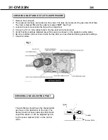
TO ACCESS FROM THE FRONT
1. Remove the glass door. Follow GLASS DOOR REMOVAL instructions within this manual.
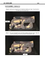
2. Remove the log set. Follow LOG PLACEMENT instructions within this manual
3. Remove the pan burner. Follow instructions for CHANGING MAIN BURNER ORIFICE within
the conversion section of this manual.
4. Remove the access cover (section set at 45 degree angle) of the firebox by removing the 1/4
“ hex head screws and lifting out. When replacing make sure to replace the gasket with a
new ceramic gasket.
5. Remove the four nuts holding the fan in place.
6. Disconnect the wires.
7. Mark all wires to be removed for proper reassembly.
8. Install new fan in reverse order.
9. Reverse these steps after new fan is installed & tested.
TO ACCESS FROM THE BACK
1.
Remove the surround by lifting up and forward.
2.
Disconnect the gas line.
3.
Disconnect the intake and exhaust liners
4.
Remove the insert from the fireplace.
5.
Remove 1/4” hex head screws and the cover plate at the back of the insert
6.
Remove the 1/4” hex head screws holding the fan bracket.
7.
Disconnect the wires.
8.
Remove the 4 nuts holding the fan to the bracket.
9.
Replace the fan with the new fan.
10. Reassemble in the reverse order.
Summary of Contents for 31-DVI33N
Page 2: ......
Page 7: ...31 DVI33N 7 RATING PLATE ...
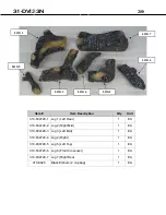
Page 20: ...31 DVI33N 20 Logs LOG 1 LOG 7 LOG 4 LOG 2 LOG 6 LOG 3 LOG 5 ...
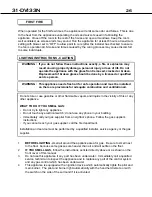
Page 27: ...31 DVI33N 27 LIGHTING INSTRUCTIONS ON RATING PLATE ...
Page 28: ...31 DVI33N 28 REMOTE CONTROL SETUP AND OPERATION ...
Page 29: ...31 DVI33N 29 REMOTE CONTROL SETUP AND OPERATION CONT ...
Page 30: ...31 DVI33N 30 REMOTE CONTROL SETUP AND OPERATION CONT ...
Page 31: ...31 DVI33N 31 REMOTE CONTROL SETUP AND OPERATION CONT ...
Page 32: ...31 DVI33N 32 REMOTE CONTROL SETUP AND OPERATION CONT ...
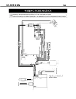
Page 38: ...31 DVI33N 38 WIRING SCHEMATICS ...
Page 43: ...31 DVI33N 43 NOTES ...
Page 44: ...31 DVI33N 44 NOTES ...
Page 46: ...Archgard Industries Ltd 7116 Beatty Drive Mission B C V2V 6B4 Canada Website www archgard com ...

