background image

2.

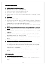
Faulty components in the unit, return for repair or have authorised technician repair.

B. Low cutting output

1.

Incorrect setting of cutting current (A), check and adjust to correct setting.

2.

Faulty components in unit, return for repair or have authorised technician repair.

C. Torch can cut but the cutting quality is poor

1.

Current (A) control set too low, increase current setting.

2.

The torch moves too fast across the workpiece, reduce cutting speed.

3.

Excessive oil or moisture in torch, hold torch 1/8 inch (3 mm) from clean surface while purging and

observe oil or moisture buildup (do not activate torch). If there are contaminants in the air additional

filtering may be needed.

4.

Lack of air pressure. Please check the air pressure and air flow, adjusting it to the correct pressure.

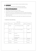
5.2 Mainframe and Selectable Packing 

Chart 5.1 list 

Serial number 

Accessories name 

Specifications and Models 

Quantity 

mountings code 

Mainframe 

ArcoCut 100i cutting power(3-380V) 

3.008.662 

Cutting torch and 

Accessories 

ST-120 non-HF Arc starter cutting gun 

7.603.040 

Earth cable 

10mm2 ,4m 

One small quick plug 

One 300A earth clamp 

6.310.322-B 

Air 

channel 

accessories 

Air tube 

Φ

12 

7.501.018 

tube hoop 

7.514.007 

Specification 

ArcoCut 100i 

8.850.148 

14


Summary of Contents for ARCOCUT G-100i

Page 1: ......

Page 2: ...ith dependable service and our extensive range of first class products Our range can be viewed at https arcoweld com au For support please contact your Authorised distributor or Arcoweld directly T 61 8 9248 3188 F 61 8 9248 3166 93 Mulgul Road MALAGA WA 6090 PO Box 3087 MALAGA DC WA 6945 Email info arcoweld com au Website www alloysteel net ...

Page 3: ...ONS 6 3 3 AIR CONNECTIONS 6 4OPERATION 7 4 1 LAYOUT OF THE FRONT AND REAR PANEL 7 4 3 CUTTING PREPARATION 9 5MAINTENANCE 12 5 1 BASIC TROUBLESHOOTING GUIDE 12 5 1 1 Basic troubles 13 5 1 2 Pilot arc troubles 13 5 1 3 Cutting troubles 13 5 2 MAINFRAME AND SELECTABLE PACKING 14 APPENDIX1 ELECTRICALPRINCIPLEDRAWING 15 APPENDIX2 TORCH PARTSAND CONNECTIONSCHEMATICDRAWING 16 II ...

Page 4: ...lation is not adequate to remove all fumes and gases The kinds of fumes and gases from the plasma arc depend on the kind of metal being used coatings on the metal and the different processes You must be very careful when cutting or cutting any metals which may contain one or more of the following Antimony Chromium Mercury Beryllium Arsenic Cobalt Nickel Lead Barium Copper Selenium Silver Cadmium M...

Page 5: ...rds may exist Hydrogen gas may be formed and trapped under aluminum workpieces when they are cut underwater or while using a water table DO NOT cut aluminum alloys underwater or on a water table unless the hydrogen gas can be eliminated or dissipated Trapped hydrogen gas that is ignited will cause an explosion NOISE Noise can cause permanent hearing loss Plasma arc processes can cause noise levels...

Page 6: ...ing to protect your skin from the arc rays and sparks Keep helmet and safety glasses in good condition Replace lenses when cracked chipped or dirty Protect others in the work area from the arc rays Use protective booths screens or shields 3 ...

Page 7: ...nsformer the main transformer and rectified by medium frequency rectifier fast recovery diode and is outputted by inductance filtering The circuit adopts current feedback control technology to insure current output stably Meanwhile the cutting current parameter can be adjusted continuously and steplessly to meet with the requirements of the cutting craft Rectify Inverter Medium frequency transform...

Page 8: ...weight kg 24 Cooling method FAN Note The above parameters are subject to change with the improvement of machines 2 3Features 1 IGBT parallel balanced current technology and digital control technology 2 Wider input voltage flexibility provides peak performance power under variable conditions 15 for steady cuts 3 EMI filter restrains the EMI transmission of the power 4 Starts without high frequency ...

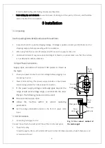
Page 9: ... your power source for correct voltage before plugging in or connecting the unit 2 Power Cord and Plug This power supply includes an input power cord and plug suitable for 3 phase power connection 3 If the power supply voltage continually goes beyond the range of safe work voltage range it will shorten the unit s lifespan The following measures can be used Ensure correct supply input Utilise the m...

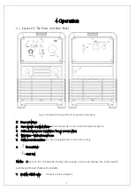
Page 10: ...t the lamp will light up 3 Cutting torch improper installation low air pressure alarm 4 Work lamp lights when unit is on 5 Cutting current regulator it is used to regulate the current when cutting 6 Normal Cut Grid Cut Note Check air for 10 seconds During this process press and release the torch switch quickly and the air check will conclude 7 Positive output cable connected to the workpiece ...

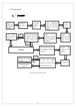
Page 11: ... Tightly connect the power cable to electrical socket outlet the input voltage refer to the section 2 technology parameters 2 Connect the air hose to the air supply connect the earth cable to the workpiece 3 Turn on the power switch the power source lamp will light up 4 Turn the RUN SET switch to SET position the air will flow then regulate the air pressure to 3 5 6bar 5 Turn the RUN SET switch to...

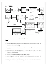
Page 12: ...ine for 5s After Initialization and the fan stops press on the torch trigger Ignite the pilot arc the max time is 10s Post air If the tip touches the workpiece and the current higher than 40A Shift to the workpiece the pilot arc will change into cutting arc Yes No The current will reduce to 40A Cutting Is the torch trigger pressed on again within the period of post air Yes Restart and continue wor...

Page 13: ...h after post air for 15s 3 Grid Cut Fig 4 3 the working flow chart Note 1 If the alarm lamp comes on when cutting loosen the switch of the torch until the alarm releases then press on the switch to restart working 2 In the automatic air test and examination mode press on the cutting torch there should be no deflection 3 After prolonged usage the surface of the electrode and nozzle will have an Oxi...

Page 14: ... You can then restart the machine b Over current The alarm is beyond resetting You must ask an authorised technician to check the machine 2 When any of the torch parts include Tip electrode shield cup and air distributor aren t installed correctly the red indicator lamp 3 lights up 3 When the air pressure is too low the indicator lamp 3 will be on continually 4 If the air distributor is not instal...

Page 15: ...urn on the machine the TIP TORCH AIR indicator lights up 1 The shield cup is not fitted correctly Turn off the power source install and screw it on properly then turn on the power source 2 The Tip or electrode is not fitted correctly Turn off the power source and install and screw the shield cup on correctly then turn on the power source D The temperature indicator lights up after the machine is w...

Page 16: ...eck the torch leads are connected to the power supply 2 Work cable is not connected to work piece or connection is poor make sure that work cable has a good connection to a clean and dry area of the workpiece 3 Faulty components in the machine return for repair or have authorised technician repair per Service Manual 4 Faulty Torch return for repair or have authorized technician repair it D Arc shu...

Page 17: ...surface while purging and observe oil or moisture buildup do not activate torch If there are contaminants in the air additional filtering may be needed 4 Lack of air pressure Please check the air pressure and air flow adjusting it to the correct pressure 5 2MainframeandSelectablePacking Chart 5 1 list Serial number Accessories name Specifications and Models Quantity mountings code 1 Mainframe Arco...

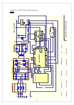
Page 18: ...Inductance T2 Circiut Transformer P Positive Output F1 Fan Hall Tr Torch K D2 D1 M ain Control Board Short Arc Board Drive Shorttest POWEROUT WA D1 D2 R1 R2 C1 C2 C3 Panel Board FAN 1 1 2 2 3 3 4 4 5 5 6 6 L1 EMC board Change Arc Testing Hall QF Air QF Guntest VM F1 Pre QF Air Valve VM Pressure Meter LG 60 Soft Starter Air Plasma Cutter Chart CUT TEST Air D1 D2 IGB T1 IGB T2 D1 D2 IGB T1 IGB T2 C5...

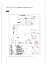
Page 19: ...d connection schematic drawing NOTE 1 Please tighten electrode properly while installing but do not tighten excessively 2 Please install the torch parts correctly otherwise the machine will go be in alarm mode after turning 16 ...

Page 20: ...3 years 3 years Torch and Leads 1 year 1 year ArcoMig Inverters Power source 3 years 3 years MIG torch Electrode holders and work leads 3 Months 3 Months Mig torch consumable items Nil Nil Gas regulator flowmeter excluding seat assemblies pressure gauges elastomer seals and O rings 1 year 1 year Regulator seat assemblies and pressure gauges 6 Months 6 Months Elastomer seal and O rings used in the ...

Page 21: ...ss or damage You are also entitled to have the goods repaired or replaced if the goods fail to be of acceptable quality and the failure does not amount to a major failure Note No employee agent or representative of Arcoweld is authorized to change this warranty in any way or grant any other warranty and Arcoweld shall not be bound by any such attempt Correction of nonconformities in the manner and...

Page 22: ...s associated with lodging the warranty claim including the return of goods to Arcoweld or our Nominated Accredited Distributor Accredited Service Provider are the responsibility of the consumer Arcoweld A B N 98 094 428 887 T 61 8 9248 3188 F 61 8 9248 3166 93 Mulgul Road MALAGA WA 6090 PO Box 3087 MALAGA DC WA 6945 Email info arcoweld com au Website www alloysteel net This warranty is provided in...

Reviews: