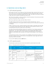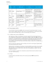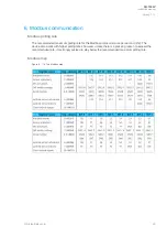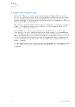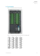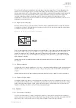
Unless the button is pressed, the latched trip relays remain active until the auxiliary power is
disconnected. All LED indications also remain active even when the auxiliary power supply is
disconnected unless the button is pressed. Please refer to the "Non-volatile memory" chapter for more
information.
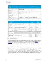
4.3.3. Input connection check
After the system setup (auto-configuration) procedure is completed, you can verify the connectivity of
all sensors and binary input channels by pressing the SET
SET push-button three (3) times within two
(2) seconds. The LEDs of the corresponding sensors and binary input channels start blinking while the
"Power" LED is already blinking. The LEDs blink as many times as there are connected sensors and
binary output channels from other units.
4.4. DIP switch settings
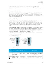
The DIP switches are used to configure the unit’s tripping logic and other functionalities. The various
trip schemes can be programmed easily by selecting the appropriate DIP switch positions. However,
the most convenient way to set the unit or a more complex arc protection system is to use Standard
Arc Schemes (SAS). Tripping can be based on arc light only, on both arc light and current thresholds.
The different tripping criteria can also be applied to BI1 to block tripping caused by natural light
sources.
The basic variant only contains one DIP switch (SW1), while the Modbus variant also has a second DIP
switch (SW2). You can find the DIP switch(es) at the back of the unit for easy access. The scheme
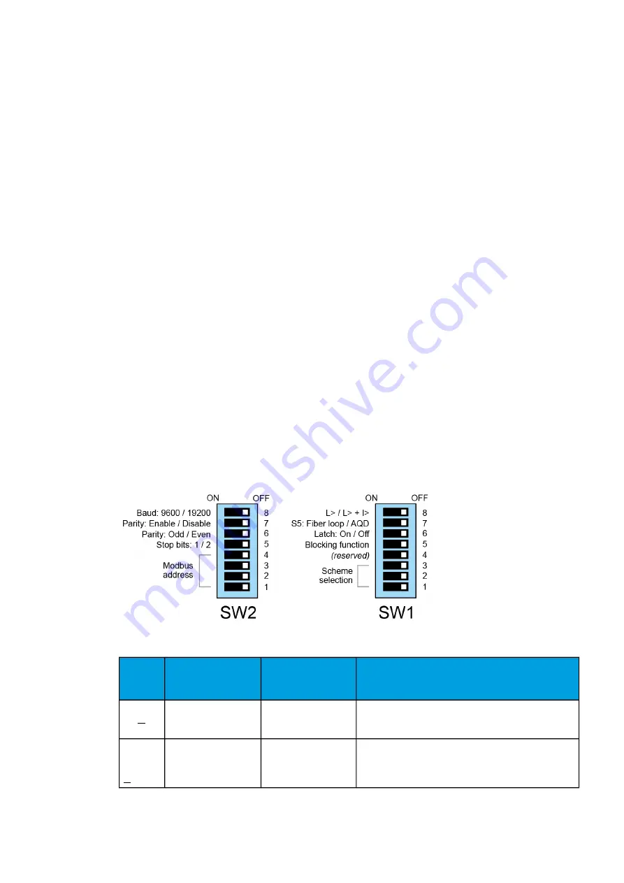
selection number is based on binary arithmetic. The Modbus address is selected with Pins 1 through 4
of the SW2 DIP switch. The address always begins with 20. For example, when Pin 1 is in the left
position (ON), the address is “21”. When Pin 4 is ON, the address is “28”.
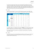
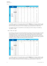
The figure below presents the two DIP switches, and the table below them gives a detailed description
of the settings for both switch groups.
Figure. 4.4. - 9. DIP switch diagrams.
Table. 4.4. - 2. DIP switch settings for SW1.
Pin
number
(name)
Function selection
ON (left position)
Off (right position)
8
(L> or
or L>
+ I>)
Selects the tripping
criteria used by all
sensor channels.
Tripping on light only
(L>).
Tripping on light (L>) and overcurrent (I>). Both are required
to occur simultaneously to trigger tripping.
7
(S5: Fiber
loop
or
or AQD)
Selects how the sensor
channel S5 is used.
The channel operates
as the fiber loop sensor
function.
The channel operates as the arc quenching system control.
The Tx terminal of S5 sends a test pulse signal to the
quenching system.
A
AQ
Q-103L
-103LV
V
Instruction manual
Version: 1.00
© Arcteq Relays Ltd
18

