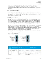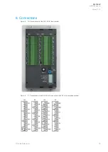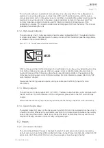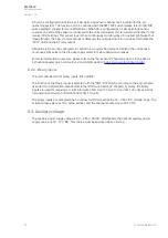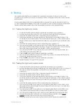
Pin
number
(name)
Function selection
ON (left position)
Off (right position)
6
(Latch:
On or
or Off)
Selects whether the trip
relays are latched or
not.
The trip relays operate
as latched.
The trip relays operate as non-latched.
5
(Blocking
function)
Selects whether the
outputs are blocked.
The outputs (T1–T4,
HSO and BO1) are
blocked.
Normal operation.
4
(reserved)
(Reserved for future
use.)
-
-
3–1
(Scheme
selection)
Selects the logic
scheme.
Please refer to the
"Scheme selection"
chapter.
Please refer to the "Scheme selection" chapter.
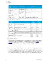
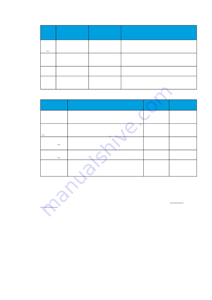
Table. 4.4. - 3. DIP switch settings for SW2.
Pin number
(name)
Function selection
ON (left
position)
Off (right
position)
8
(Baud: 9600
or
or 19200)
Selects the baud rate used by Modbus.
The baud rate is
9600.
The baud rate is
19200.
7
(Parity: Enable
or
or Disable)
Selects whether the parity bit is enabled or not.
The parity bit is
enabled.
The parity bit is
disabled.
6
(Parity: Odd or
or
Even)
Selects whether the parity makes the string's total number
odd or even.
The total number
is odd.
The total number is
even.
5
(Stop bits: 1 or
or 2)
Selects the number of stop bits used to indicate the end of
data transmission.
One (1) stop bit is
used.
Two (2) stop bits
are used.
4–1
(Modbus address)
Defines the Modbus address.
Pin 1: 1
Pin 2: 2
Pin 3: 4
Pin 4: 8
Pin 1: 0
Pin 2: 0
Pin 3: 0
Pin 4: 0
4.4.1. Scheme selection
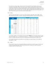
This chapter describes the schemes available for both variants of the unit. The schemes are configured
using the first DIP switch (SW1) and its pins 1…3 ("Scheme selection"). For detailed instructions on
each of the available schemes please refer to the AQ-SAS™ booklet (can be found at
arcteq.fi/
downloads/
). Please note that there are four booklets: two are for schemes based on IEC standards
(MV and LV versions) and the other two for schemes based on ANSI standards (MV and LV versions).
4.4.2. Available logic schemes
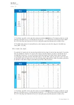
Below you can see descriptions of all the logic schemes available to the AQ-103LV unit. The basic logic
is the same in all the logic schemes: BO1 and BI2 are always tripped by light (L>), whereas BI1 is
always tripped by overcurrent (I>). Regardless of the selected logic scheme, BO1 activates whenever
the sensors S1–S4, S5, S6–S15 or BI2 activates. You can select between light-only tripping and light-
and-overcurrent tripping with DIP switch 1 (SW1: 8). This selection affects all trip relays (T1–T4) as well
as the high-speed output (HSO). This is also true of the DIP switch that determines latching (SW1: 6).
A
AQ
Q-103L
-103LV
V
Instruction manual
Version: 1.00
19
© Arcteq Relays Ltd

