background image

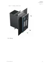
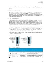
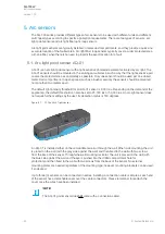
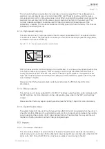
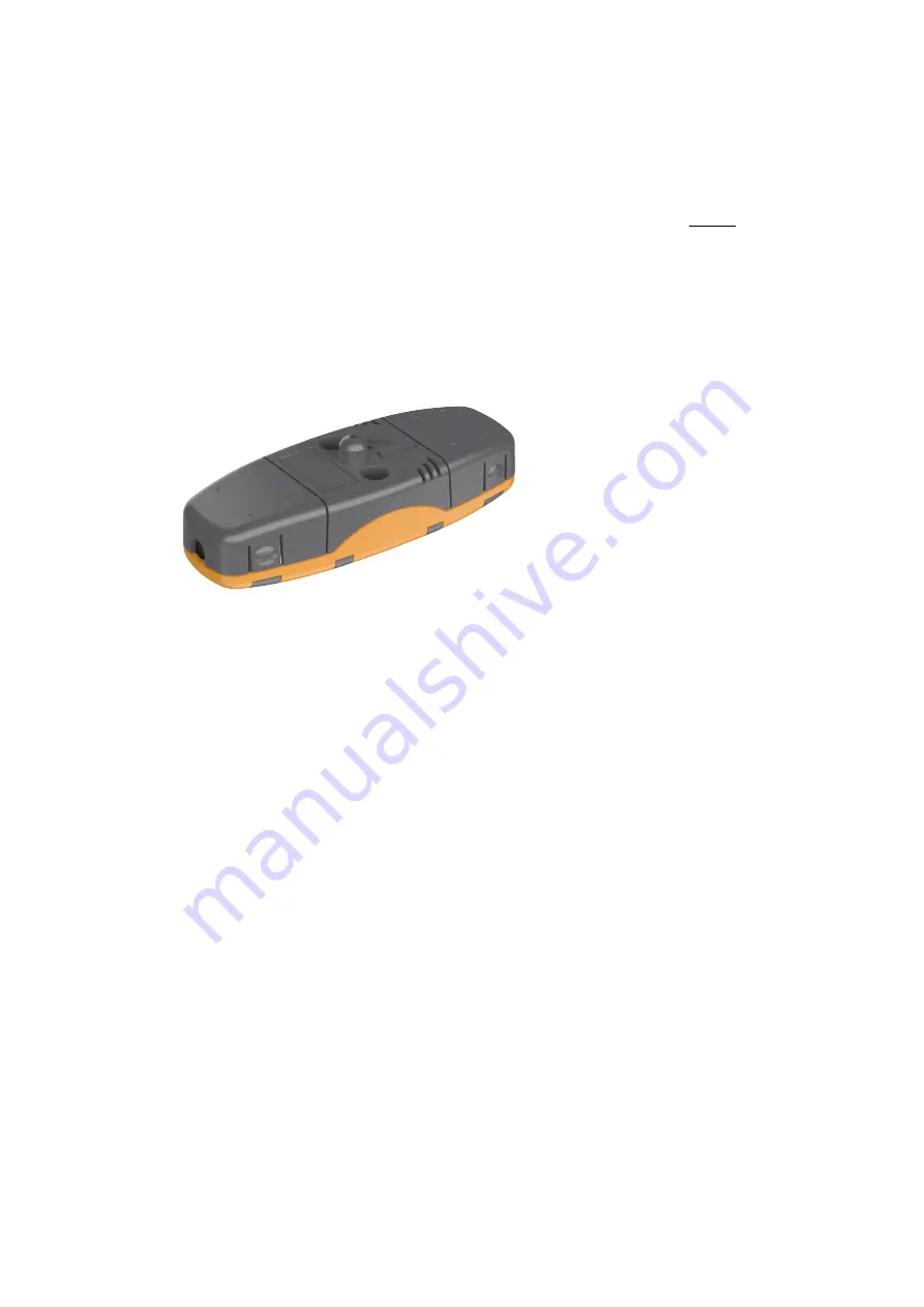
5.2. Arc light and pressure point sensor AQ-02

AQ-02 is an arc light and pressure point sensor that comes with arc light detection and ambient
pressure detection. The AQ-02 sensors should be mounted in the switchgear cubicles in such a way
that the light-sensitive part covers the protected area as completely as possible. Only one sensor
should be used per one closed metal-clad compartment. The AQ-02 sensors c

canno

annott be installed in

open spaces.

The default light intensity threshold for an AQ-02 sensor is 8,000 lux. Depending on the demand of the
application, the default threshold can also be set to 25,000 lux or 50,000 lux. An arc light sensor does
not require further settings by the user. Its detection radius is 180 degrees. The pressure threshold is
fixed at 0.2 bar above ambient pressure.

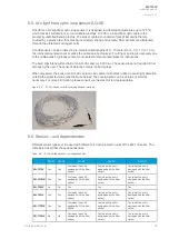
Figure. 5.2. - 11. AQ-02 arc light and pressure point sensor.

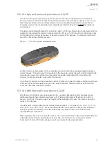
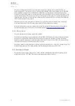
An AQ-02 can only be installed on the compartment wall as not to block pressure detection located
next to "the eye". The unit placed on the wall (with the gray side against the wall), and then fixed to the
wall with two screws. No external mounting plates are needed regardless of the mounting type;
however, mounting brackets can be used if so desired.

Up to three (3) sensors can be connected in series. Installing a connection cable is simple as each end
of the sensor has a detachable cover over the cable connectors. Please remember to reattach the
cover once the wires have been installed.

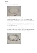
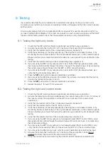
5.3. Arc light fiber optic loop sensor AQ-06

AQ-06 is an arc light fiber optic loop sensor, which is a plastic fiber optic cable. Fiber sensors are
distributed through the protected switchgear cells. The fixed light intensity threshold of an AQ-06
sensor is 8,000 lux. The sensor does not require further settings by the user. The sensor's detection
radius is 360 degrees.

AQ-06 sensors can be ordered in pre-manufactured lengths of 3…40 meters (3 m, 5 m, 10 m, 15 m,
20 m, 25 m, 30 m, 35 m, 40 m). It is not recommended to cut or splice the cable on-site. However, if
cutting or splicing is necessary due to the cable breaking, please contact your nearest Arcteq
representative for instructions.

When requested, the ends of an AQ-06 cable can be covered with black rubber to avoid light detection
outside the protected zone (see the figure below). The covered area can be as large or small as
necessary. For more information, please consult your nearest Arcteq representative.

A

AQ

Q-103L

-103LV

V

Instruction manual

Version: 1.00

© Arcteq Relays Ltd

24

Summary of Contents for AQ-103

Page 1: ...AQ 103LV Arc flash protection unit Instruction manual ...

Page 2: ...t fiber optic loop sensor AQ 08 26 5 6 Sensor unit dependencies 26 5 7 Connecting sensors 27 6 Modbus communic 6 Modbus communica ation tion 28 28 7 S 7 Sy yst stem self super em self supervision vision 29 29 8 Connections 8 Connections 30 30 8 1 Outputs 31 8 1 1 Trip relays 31 8 1 2 High speed output s 32 8 1 3 Binary outputs 32 8 1 4 System failure relay 32 8 2 Inputs 32 8 2 1 Arc sensor channel...

Page 3: ...ntal conditions 41 11 10 Casing and packaging 41 12 Or 12 Ordering inf dering informa ormation tion 42 42 13 Contact and r 13 Contact and re ef fer erence inf ence informa ormation tion 43 43 A AQ Q 103L 103LV V Instruction manual Version 1 00 Arcteq Relays Ltd 2 ...

Page 4: ... the warranty obligations of the manufacturer Arcteq Relays Ltd The manufacturer expressly disclaims any and all liability for any damages and or losses caused due to a failure to comply with the instructions contained herein or caused by persons who do not fulfil the aforementioned requirements Furthermore the manufacturer shall not be liable for possible errors in this document Please note that ...

Page 5: ...Copyright Copyright Arcteq Relays Ltd 2020 All rights reserved A AQ Q 103L 103LV V Instruction manual Version 1 00 Arcteq Relays Ltd 4 ...

Page 6: ...1 Manual revision notes R Re evision vision 1 00 1 00 Date September 2020 Changes The first revision of the manual A AQ Q 103L 103LV V Instruction manual Version 1 00 5 Arcteq Relays Ltd ...

Page 7: ...e read only memory HSO high speed output LED light emitting diode LV low voltage MV medium voltage NC normally closed NO normally open PCB printed circuit board QD quenching device RF radio frequency Rx receiver SAS standard arc scheme SF system failure Tx transceiver μP microprocessor A AQ Q 103L 103LV V Instruction manual Version 1 00 Arcteq Relays Ltd 6 ...

Page 8: ...hese include utilities and power plants both traditional and renewable various heavy industry applications oil gas mining steel etc as well as commercial and institutional electrical systems While AQ 103LV is suitable for MV use it is designed for LV switchgears and for motor control center applications in both new and retrofitted installations 3 1 Dimensions and installation AQ 103LV can be eithe...

Page 9: ...Figure 3 1 1 Dimensions of the device The image below presents the dimensions of the cut put need for mounting the unit on a panel A AQ Q 103L 103LV V Instruction manual Version 1 00 Arcteq Relays Ltd 8 ...

Page 10: ...Figure 3 1 2 Cut out for panel mounting a unit The following image illustrates how the unit is installed into a cut out A AQ Q 103L 103LV V Instruction manual Version 1 00 9 Arcteq Relays Ltd ...

Page 11: ...Figure 3 1 3 Installing a unit into a cut out 3 2 Wiring A AQ Q 103L 103LV V Instruction manual Version 1 00 Arcteq Relays Ltd 10 ...

Page 12: ...Figure 3 2 4 Wiring diagram for AQ 103LV A AQ Q 103L 103LV V Instruction manual Version 1 00 11 Arcteq Relays Ltd ...

Page 13: ...odbus communication The following list presents the main features of the unit 92 265 V AC DC auxiliary power supply or or 18 72 V DC auxiliary power optional fourteen 14 arc point channels one 1 fiber loop sensor channel or or AQ 1000 control optional two 2 binary inputs with a nominal operation voltage of 24 V DC one 1 high speed semiconductor trip output three 3 normally open trip relay outputs ...

Page 14: ...ation LEDs one 1 push button Figure 3 3 6 Arc protection unit AQ 103LV 3 4 Simplified block diagram The figures below present the main components of the AQ 103LV variants the basic unit and the Modbus unit A AQ Q 103L 103LV V Instruction manual Version 1 00 13 Arcteq Relays Ltd ...

Page 15: ...Figure 3 4 7 Simplified block diagram of AQ 103LV A AQ Q 103L 103LV V Instruction manual Version 1 00 Arcteq Relays Ltd 14 ...

Page 16: ...Figure 3 4 8 Simplified block diagram of the AQ 103LV Modbus variant A AQ Q 103L 103LV V Instruction manual Version 1 00 15 Arcteq Relays Ltd ...

Page 17: ... active for longer than 1 5 ms the corresponding LED turns on that is they become latched This also happens when a trip situation occurs The trip outputs are controlled with DIP switch settings All activation and trip indication LEDs are latched even if the DIP switch settings are in the non latched mode All LED indications are stored in the non volatile memory EPROM to help identify the necessary...

Page 18: ... as auto configuration for resetting the indicator LEDs and the latched output relays as well as for checking the input connection 4 3 1 System setup auto configuration After all sensors and binary lines have been connected a system setup procedure also known as auto configuration must be performed The sequence is initialized by pressing the SET SET push button for two seconds This causes the sens...

Page 19: ...esholds The different tripping criteria can also be applied to BI1 to block tripping caused by natural light sources The basic variant only contains one DIP switch SW1 while the Modbus variant also has a second DIP switch SW2 You can find the DIP switch es at the back of the unit for easy access The scheme selection number is based on binary arithmetic The Modbus address is selected with Pins 1 th...

Page 20: ...d Two 2 stop bits are used 4 1 Modbus address Defines the Modbus address Pin 1 1 Pin 2 2 Pin 3 4 Pin 4 8 Pin 1 0 Pin 2 0 Pin 3 0 Pin 4 0 4 4 1 Scheme selection This chapter describes the schemes available for both variants of the unit The schemes are configured using the first DIP switch SW1 and its pins 1 3 Scheme selection For detailed instructions on each of the available schemes please refer t...

Page 21: ...d the AQD control When the blocking function is selected it prevents all tripping activations apart from LED activations 1 The binary input BI1 can be used to receive an external curr current ent signal The tripping criterion can be selected to be light only L or both light and current L I When the current input function SW1 8 is OFF the relay must receive both current and light signals simultaneo...

Page 22: ...itors the bus coupler circuit breaker and it controls the trip relays T1 T3 and T4 which is the main input of the other side of the bus coupler circuit breaker S14 also monitors the AQD control The rest of the sensors control T1 and T3 as well as the AQD control All sensors can also trip the high speed output HSO When the blocking function is selected it prevents all tripping activations apart fro...

Page 23: ...pervision even if auxiliary power is lost temporarily Additionally all LED indications are stored in the non volatile memory to provide a quick recovery of the system status indication This feature is especially important if tripping causes the unit to lose its auxiliary power The non volatile memory does not require a power supply to maintain the information and it retains the settings and the in...

Page 24: ...for an AQ 01 sensor is 8 000 lux Depending on the demand of the application the default threshold can also be set to 25 000 lux or 50 000 lux An arc light sensor does not require further settings by the user Its detection radius is 180 degrees Figure 5 1 10 The AQ 01 light sensor An AQ 01 is installed either on the compartment wall or through the wall When wall mounting the unit is placed on the w...

Page 25: ... the mounting type however mounting brackets can be used if so desired Up to three 3 sensors can be connected in series Installing a connection cable is simple as each end of the sensor has a detachable cover over the cable connectors Please remember to reattach the cover once the wires have been installed 5 3 Arc light fiber optic loop sensor AQ 06 AQ 06 is an arc light fiber optic loop sensor wh...

Page 26: ...commended to cut or splice the cable on site However if cutting or splicing is necessary due to the cable breaking please contact your nearest Arcteq representative for instructions The fixed light intensity threshold of an AQ 07 sensor is 8 000 lux The sensor does not require further settings by the user The sensor s detection radius is 360 degrees When requested the ends of an AQ 07 cable can be...

Page 27: ... nearest Arcteq representative Figure 5 5 14 AQ 08 sensor with covered ends and terminals 5 6 Sensor unit dependencies Different sensor types can be used with different arc flash protection units of the AQ 100 series The table below describes those dependencies Table 5 6 4 Low voltage sensor unit dependencies AQ 01 AQ 02 AQ 06 AQ 07 AQ 08 A AQ Q 101L 101LV V Yes Yes Yes when the unit is equipped w...

Page 28: ...s How to connect fiber sensors 1 Drill holes on the compartment wall and cover any sharp edges 2 Run the fiber through the holes and fasten it to the protected area 3 Connect the sensor terminals into the Tx and Rx slots at the back of the unit Please note that AQ 07 and AQ 08 glass fibers can be covered with additional tubing if the fiber sensor s placing requires the blocking of unwanted light a...

Page 29: ... second 2 s The device also works with higher polling rates however unless there is a pressing reason to exceed the recommended rate it is strongly advised to stay below the recommended maximum polling rate Modbus map Figure 6 15 The Modbus map A AQ Q 103L 103LV V Instruction manual Version 1 00 Arcteq Relays Ltd 28 ...

Page 30: ...it If a sensor failure occurs the unit will go into Error mode The Error LED turns on the SF relay releases and the LED of the corresponding faulty sensor channel starts blinking In this situation the unit is still in the protection mode although the faulty sensor channel is blocked If the error is resolved the unit automatically clears the system failure status enegizing the SF relay and turning ...

Page 31: ...igure 8 16 Rear terminals of the AQ 103 LV basic variant Figure 8 17 Connections of the AQ 103 LV basic variant with SF in de energized position A AQ Q 103L 103LV V Instruction manual Version 1 00 Arcteq Relays Ltd 30 ...

Page 32: ... in de energized position 8 1 Outputs 8 1 1 Trip relays This unit has four 4 integrated trip relays for tripping circuit breakers according to the scheme selection Their type is normally open NO Optionally T3 can be selected as normally closed NC A AQ Q 103L 103LV V Instruction manual Version 1 00 31 Arcteq Relays Ltd ...

Page 33: ...units without a need for signal amplifiers The operation of the high speed output depends on the DIP switch settings for more information please refer to the DIP switch settings chapter Please note that the high speed output is polarity sensitive see the Wiring chapter for more information 8 1 3 Binary outputs The unit has one 1 binary output BO1 24 VDC The binary output function can be configured...

Page 34: ...on on sensors please refer to the Arc sensors chapter as well as to the AQ 0x instruction booklet which can be found on Arcteq s website https www arcteq fi downloads 8 2 2 Binary inputs The unit contains two 2 binary inputs BI1 and BI2 The function of the binary inputs is selected with the SW1 DIP switch according to the logic scheme used for more information please refer to the DIP switch settin...

Page 35: ...BI2 binary input as the master trip activate it and verify that the trip has occurred by repeating the steps 4 and 5 10 Press the SET SET push button to reset all indications and latches 11 Repeat the steps 1 through 10 for all sensors 9 2 Testing the light and current mode 1 Check that the DIP switch settings are positioned according to your application 2 Activate the following two things simulta...

Page 36: ...for the type test reports However if it is deemed necessary you can conduct an on site timing test with the following instructions 1 Use a calibrated relay test set 2 Connect one of the test set s outputs to a camera flash Canon xx or equivalent to initialize the flash and to configure the set s timer to start simultaneously with the flash 3 Connect one of the AQ 110 unit s trip outputs T1 T2 T3 T...

Page 37: ...A AQ Q 103L 103LV V Instruction manual Version 1 00 Arcteq Relays Ltd 36 ...

Page 38: ...g equipment especially the camera flash intensity see the Testing chapter for more information The trip relay does not operate even when the sensor is activated Check the DIP switch settings see the DIP switch settings chapter for more information The system gives an alarm that cannot be cleared or installed Check that each sensor channel only has one sensor connected to it A AQ Q 103L 103LV V Ins...

Page 39: ...A at 110 V DC Contact material AgNi 90 10 When the time constant L R 40 ms 11 2 2 Binary output s Rated voltage 24 V DC Rated current max 20 mA Number of outputs 1 11 2 3 High speed output s Number of outputs 1 Rated voltage 250 VDC Carry continuous make and carry for 3 s make and carry for 0 5 s 2 A 6 A 15 A Breaking capacity DC 1 A 110 W Contact material Semiconductor When the time constant L R ...

Page 40: ...ndby current 90 mA 11 5 Sensors AQ 01 point sensor Light intensity threshold 8 000 lux 25 000 lux 50 000 lux Detection radius 180º Mechanical protection of the whole sensor Mechanical protection for the active light detection part of the sensor IP 20 IP 60 Sensor cable specification Shielded twisted pair 0 75 mm2 AWG 20 Maximum sensor cable length per channel 200 m Operating temperature 20 85 ºC A...

Page 41: ...adius 5 cm Operating temperature 40 85 ºC AQ 07 fiber optic loop sensor Material Covered glass fiber Light intensity threshold 8 000 lux Cable length min max 3 50 m Cable diameter 1 2 mm Detection radius 360º Bending radius 1 cm Operating temperature 40 85 ºC AQ 08 fiber optic loop sensor Material Covered glass fiber Light intensity threshold 8 000 lux Cable length min max 3 15 m Cable diameter 1 ...

Page 42: ... f 150 kHz 80 MHz 10 V 11 7 Voltage tests Insulation test voltage IEC 60255 5 2 kV 50 Hz 1 min Impulse test voltage IEC 60255 5 5 kV 1 2 50 µs 0 5 J 11 8 Mechanical tests Vibration test 2 13 2 Hz 3 5 mm 13 2 100 Hz 1 0 g Shock bump test IEC 60255 21 2 20 g 1 000 bumps dir 11 9 Environmental conditions Specified ambient service temperature 35 70 ºC Transportation and storage temperature 40 70 ºC Re...

Page 43: ...ptic loop sensors Accessories Order code Description Note Manufacturer AQX099 Wall bracket For AQ 101 AQ 101S and AQ 102 units MV and LV Arcteq Ltd AQX100 Wall bracket For AQ 103 and AQ 110x variants MV and LV Arcteq Ltd A AQ Q 103L 103LV V Instruction manual Version 1 00 Arcteq Relays Ltd 42 ...

Page 44: ...and postal address Kvartsikatu 2 A 1 65300 Vaasa Finland Contacts Phone 358 10 3221 370 Fax 358 10 3221 389 Website general arcteq fi Website technical support support arcteq fi E mail sales sales arcteq fi A AQ Q 103L 103LV V Instruction manual Version 1 00 43 Arcteq Relays Ltd ...

Reviews: