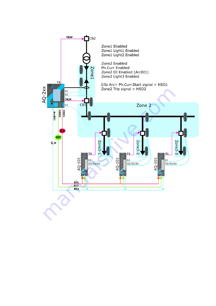
Figure. 5.3.14 - 137. Scheme IA1 (with AQ-101 arc protection relays).
To set the zones for the AQ-2xx models sensor channels start by enabling the protected zones (in this
case, Zones 1 and 2). Then define which sensor channels are sensing which zones (in this case,
sensor channels S1 and S2 are protecting Zone 1). Enable Light 1 of Zone 1 as well as Light 2 of Zone
2. The sensor channel S3 deals with Zone 2. Enable Light 3 of Zone 2. The high-speed output contacts
HSO1 and HSO2 have been set to send overcurrent and master trip signals to the AQ-101 arc
protection relays. The AQ-100 series units send out test pulses in specific intervals to check the health
of the wiring between the AQ-100 series units. The parameter
I/I0 Arc> Self supervision test pulse
should be activated when connecting the AQ-100 series units to the AQ-200 series arc protection card
to prevent the pulses from activating ArcBI1.
The next example is almost like the previous one: it is also a single-line diagram with AQ-2xx series
relays. However, this time each outgoing feeder has an AQ-2xx protection relay instead of an AQ-101
arc protection relay.
A
AQ
Q-C213
-C213
Instruction manual
Version: 2.04
195


