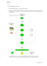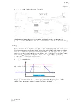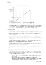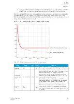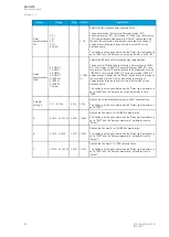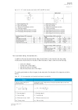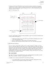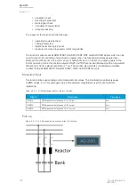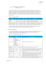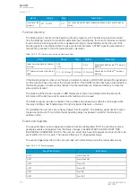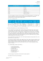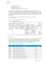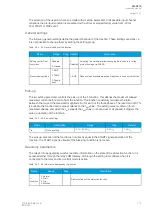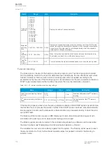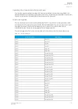
Figure. 5.4.2 - 88. Unbalance measurement and natural unbalance compensation.
Na
Nattural unbalance compensa
ural unbalance compensation
tion
In practice, the unbalance seen by an unbalance relay is the result of losing individual capacitor units
(or elements) and of the inherent system and bank unbalances. The primary unbalance, which exists
on all capacitor bank installations (with or without fuses), is due to the system voltage unbalance and to
capacitor manufacturing tolerances. Secondary unbalance errors are introduced by sensing device
tolerances and variation as well as by relative changes in capacitance due to the difference in capacitor
unit temperatures in the bank. If the inherent unbalance error approaches 50 % of the alarm setting,
there needs to be compensation so that the relay alarms as specified when a unit or an element fails.
Please note that harmonic voltages and currents can influence the operation of the unbalance relay
unless a power frequency band-pass or other appropriate filtering is provided.
A
About the r
bout the rela
elay opera
y operating time
ting time
The time delay of the unbalance relay trip should be minimized to reduce damage from an arcing fault
within the bank's structure as well as to prevent the remaining capacitor units' exposure to overvoltage
conditions beyond their permissible limits.
The unbalance trip relay should have enough time delay to avoid false operations due to inrush, to
system earth faults, to switching of nearby equipment, and to non-simultaneous pole operation of the
energizing switch. For most applications, 0.1 s should be adequate. For unbalance relaying systems
that would operate on a system voltage unbalance, a delay slightly longer than the upstream protection
fault clearing time is required to avoid tripping due to a system fault. Longer delays increase the
probability of bank failures.
A
AQ
Q-C215
-C215
Instruction manual
Version: 2.07
© Arcteq Relays Ltd
IM00040
101

