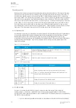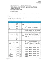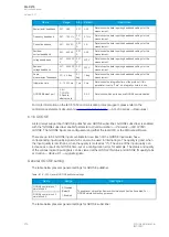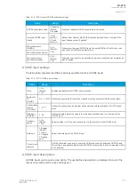
The pick-up activation of the function is not directly equal to the START signal generation of the
function. The START signal is allowed if the blocking condition is not active.
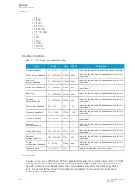
Comparator modes
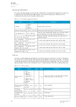
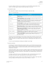
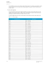
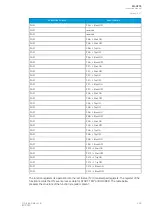
When setting the comparators, the user must first choose a comparator mode.
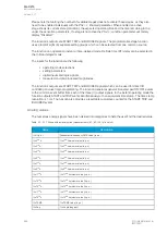
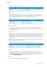
Table. 5.7 - 212. Comparator modes
Mode
Description
0: Over >
G
Grrea
eatter than
er than. If the measured signal is greater than the set pick-up level, the comparison
condition is fulfilled.
1: Over (abs) >
G
Grrea
eatter than (
er than (absol
absolut
utee)). If the absolute value of the measured signal is greater than the set
pick-up level, the comparison condition is fulfilled.
2: Under <
LLess than
ess than. If the measured signal is less than the set pick-up level, the comparison condition
is fulfilled. The user can also set a blocking limit: the comparison is not active when the
measured value is less than the set blocking limit.
3: Under (abs) <
LLess than (
ess than (absol
absolut
utee)). If the absolute value of the measured signal is less than the set pick-up
level, the comparison condition is fulfilled. The user can also set a blocking limit: the
comparison is not active when the measured value is less than the set blocking limit.
4: Delta set (%) +/- >
R
Rela
elativ
tive change o
e change ovver time
er time. If the measured signal changes more than the set relative pick-up
value in 20 ms, the comparison condition is fulfilled. The condition is dependent on direction.
5: Delta abs (%) >
R
Rela
elativ
tive change o
e change ovver time (
er time (absol
absolut
utee)). If the measured signal changes more than the set
relative pick-up value in 20 ms in either direction, the comparison condition is fulfilled. The
condition is not dependent on direction.
6: Delta +/- measval
C
Change o
hange ovver time
er time. If the measured signal changes more than the set pick-up value in 20 ms,
the comparison condition is fulfilled. The condition is dependent on direction.
7: Delta abs measval
C
Change o
hange ovver time (
er time (absol
absolut
utee)). If the measured signal changes more than the set pick-up value
in 20 ms in either direction, the comparison condition is fulfilled. The condition is not
dependent on direction.
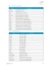
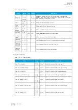
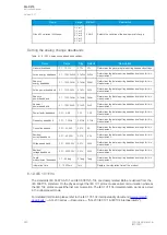
The pick-up level is set individually for each comparison. When setting up the pick-up level, the user
needs to take into account the modes in use as well as the desired action. The pick-up limit can be
set either as positive or as negative. Each pick-up level has a separate hysteresis setting which is 3 %
by default.
The user can set the operating and releasing time delays for each stage.
Function blocking
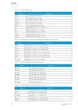
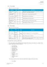
The block signal is checked in the beginning of each program cycle. The blocking signal is received
from the blocking matrix in the function's dedicated input. If the blocking signal is not activated when
the pick-up element activates, a START signal is generated and the function proceeds to the time
characteristics calculation.
If the blocking signal is active when the pick-up element activates, a BLOCKED signal is generated and
the function does not process the situation further. If the START function has been activated before the
blocking signal, it resets and the release time characteristics are processed similarly to when the pick-
up signal is reset.
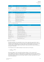
The blocking of the function causes an HMI display event and a time-stamped blocking event with
information of the startup values of the selected signal and its fault type to be issued.
The blocking signal can also be tested in the commissioning phase by a software switch signal when
the relay's testing mode "Enable stage forcing" is activated (
General
→
Device).
A
AQ
Q-C215
-C215
Instruction manual
Version: 2.07
© Arcteq Relays Ltd
IM00040
267

