Signals
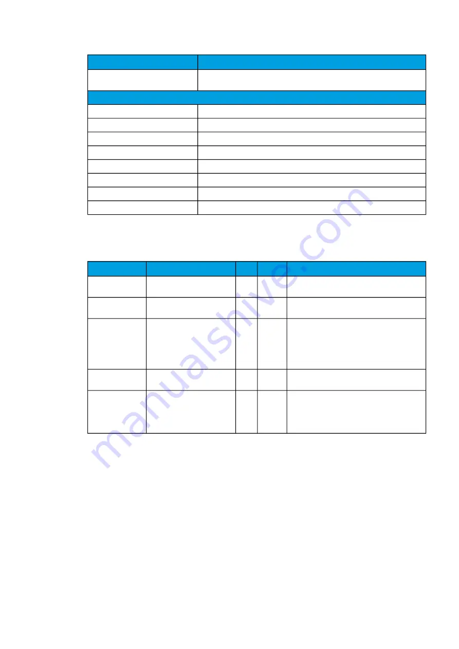
Description
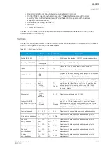
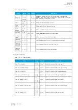
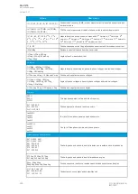
YL1angle, YL2angle, YL3angle,
Y0angle
Admittance angles.
Others
System f.
Used tracking frequency at the moment.
Ref f1
Reference frequency 1.
Ref f2
Reference frequency 2.
M thermal T
Motor thermal temperature.
F thermal T
Feeder thermal temperature.
T thermal T
Transformer thermal temperature.
RTD meas 1…16
RTD measurement channels 1…16.
Ext RTD meas 1…8
External RTD measurement channels 1…8 (ADAM module).
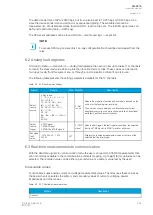
Settings
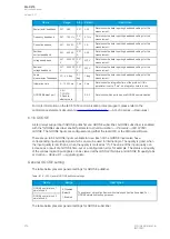
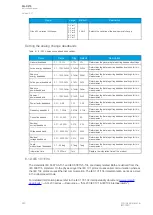
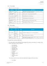
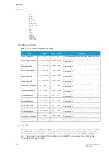
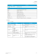
Table. 6.3 - 238. Settings.
Name
Range
Step Default
Description
Measurement value
recorder mode
0: Disabled
1: Activated
-
0:
Disabled
Activates and disables the real-time signals to
communication.
Scale current
values to primary
0: No
1: Yes
-
0: No
Selects whether or not values are scaled to
primary.
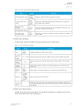
Slot X magnitude
selection
0: Currents
1: Voltages
2: Powers
3: Impedance (ZRX) and
admittance (YGB)
4: Others
-
0:
Currents
Selects the measured magnitude catecory of the
chosen slot.
Slot X magnitude
Described in table above
("Available measured values")
-
-
Selects the magnituge in the previously selected
category.
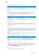
Magnitude X
-10 000 000.000…10 000
000.000
0.001 -
Displays the measured value of the selected
magnitude of the selected slot.
The unit depends on the selected magnitude
(either amperes, volts, or per-unit values).
A
AQ
Q-C215
-C215
Instruction manual
Version: 2.07
© Arcteq Relays Ltd
IM00040
285

