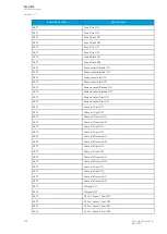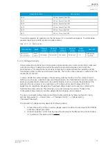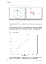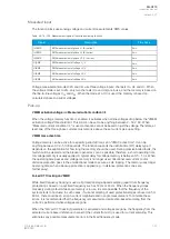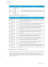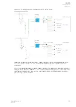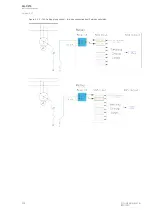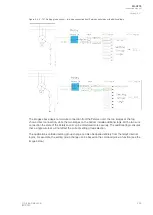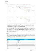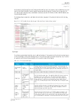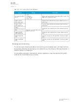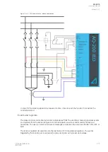
Figure. 5.4.14 - 136. Frequency reference channels.
For example, let us say a 500 A current is measured on the primary side while the fixed frequency is set
to 50 Hz. This results in the frequency dropping to 46 Hz, while the actual current measurement would
be 460 A. Therefore, the system would have an error of 40 A.
Events
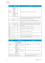
The voltage memory function (abbreviated "M1VT" in event block names) generates events from the
status changes in various activities. The user can select which event messages are stored in the main
event buffer: ON, OFF, or both.
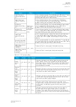
Table. 5.4.14 - 143. Event messages.
Event block name
Event names
M1VT1
Voltage memory enabled
M1VT1
Voltage memory disabled
M1VT1
Voltage low detected ON
M1VT1
Voltage low detected OFF
M1VT1
Current high detected ON
M1VT1
Current high detected OFF
M1VT1
Frequency tracked from CT ON
M1VT1
Frequency tracked from CT OFF
M1VT1
Using Voltage memory ON
M1VT1
Using Voltage memory OFF
M1VT1
Voltage memory blocked ON
M1VT1
Voltage memory blocked OFF
5.5 Control functions
5.5.1 Common signals
Common signals function has all protection function start and trip signals internally connected to
Common START and TRIP output signals. When any of the activated protection functions generate a
START or a TRIP signal, Common signals function will also generate the same signal.
The function's outputs are START and TRIP signals which can be used for direct I/O controlling and
user logic programming. The function generates general time-stamped ON/OFF events to the common
event buffer from each of the two (2) output signals. The time stamp resolution is 1 ms. The function
also provides a resettable cumulative counter for the START and TRIP events.
A
AQ
Q-C215
-C215
Instruction manual
Version: 2.07
198
© Arcteq Relays Ltd
IM00040

