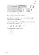
θ
End
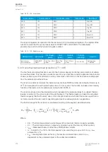
= (I
meas
/I
N
)
2
Where:
• I
meas
= the measured current
• I
N
= the calculated effective nominal current
Calcula
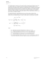
Calculatted time constant:
ed time constant:
τ=e
(-0.005[s]×(Tc[min]×60)[s])
Where:
• e = Euler's number
• τ
c
= the time constant set by the user
• 0.005s is the program cycle time
Calcula
Calculatted activ
ed active thermal sta
e thermal stattus
us::
θ
Calc
= ((θ
-1
- θ
End
)×τ) + θ
End
Where:
• θ
-1
= previous cycle calculation result (integrating function needs the memory to operate)
• θ
End
= the calculated end heating (dependent on the measured current)
• τ = the calculated time constant
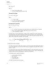
The tripping time can be calculated based on these previous calculations according to the following
formula (the result in seconds). With this base information the tripping time can be calculated with the
formula above (in seconds) when replacing the θ
Calc
with the value of the thermal level which from the
tripping time is wanted to be calculated (in per-unit value).
Function inputs and outputs
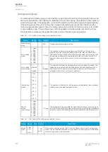
The blocking signal and the setting group selection control the operating characteristics of the function
during normal operation, i.e. the user or user-defined logic can change function parameters while the
function is running.
The outputs of the function are the TRIP and BLOCKED signals. The overvoltage function uses a total
of eight (8) separate setting groups which can be selected from one common source. Additionally, the
function's operating mode can be changed via the setting group selection.
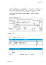
The operational logic consists of the following:
• input magnitude processing
• thermal replica
• block signal check
• output processing.
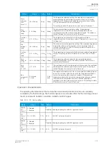
The inputs for the function are the following:
A
AQ
Q-F205
-F205
Instruction manual
Version: 2.04
230
© Arcteq Relays Ltd
IM00013
Summary of Contents for AQ F205
Page 1: ...AQ F205 Feeder protection IED Instruction manual ...
Page 2: ......

