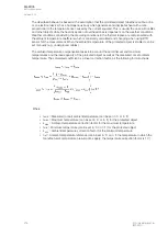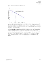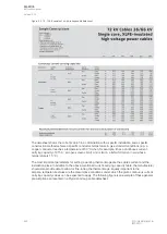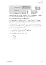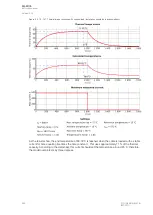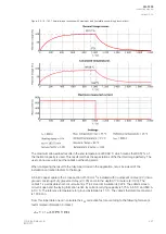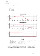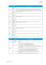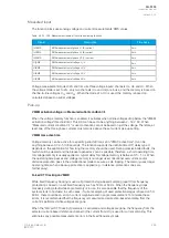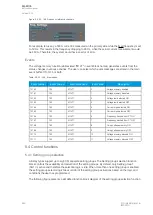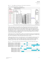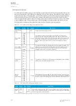
Table. 5.3.19 - 157. Settings for thermal replica.
Name
Range
Step
Default
Description
IN thermal
cap
current
0.10…40.00xI
n
0.01xI
n
1.00xI
n
The current for the 100 % thermal capacity to be used (the pick-up
current in p.u., with t
max
achieved in time τ x 5).
Set or
Estimate
tau (t
const)
0: Set
1: Estimate
-
0: Set
The selection of the time constant setting. If "Set" is selected, the Tau (t
const) setting is available and the time constant to be used can be set
there. If "Estimate" is selected, the cable's initial data parameters are
visible.
Tau (t
const)
0.1…500.0min
0.1min
10.0min
The time constant setting. This time constant is used for heating and
cooling of the protected object. This setting is visible if the "Set" is
selected for the "Set or Estimate tau" setting.
Max.
perm.
OC.
current
(norm
**ik**1s)
1…1 000
000A
1A
75 000A
The maximum-rated short-circuit current of the protected object
(cable). Usually this value is presented as a one second value. This
setting is visible if "Estimate" is selected for the "Set or Estimate tau"
setting.
Max. OC.
time
(norm 1 s)
0.1…5s
0.1s
1.0s
The time of the maximum-rated short-circuit current of the protected
object (usually 1 s). This setting is visible if "Estimate" is selected for the
"Set or Estimate tau" setting.
Nominal
current
1…1 000
000A
1A
700A
The rated nominal current in the primary value of the protected object
under nominal-rated conditions. This setting is visible if "Estimate" is
selected for the "Set or Estimate tau" setting.
Estimated
tau
0…1800min
0.005min
191.3min
(from
defaults)
The estimated result which is used for the thermal replica's time
constant. After the previous three required parameters are set the IED
will calculate this value. This setting is visible if "Estimate" is selected for
the "Set or Estimate tau" setting.
k
SF
(service
factor)
0.01…5.00
0.01
1.00
The service factor which corrects the value of the maximum allowed
current according to installation and other conditions varying from the
presumptive conditions.
Cold reset
default
theta
0.0…150.0%
0.1%
60.0%
The thermal image status in the restart of the function/ IED. The value
is given in percentages of the used thermal capacity of the protected
object. It is also possible to reset the thermal element.
This parameter can be used when testing the function to manually set
the current thermal cap to any value.
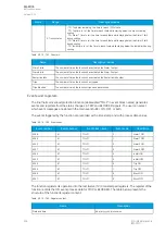
Table. 5.3.19 - 158. Environmental settings
Name
Range
Step
Default
Description
Object
max.
temp. (t
max
= 100%)
0…500deg
1deg
90deg
The maximum allowed temperature for the protected object. The default
suits for Celsius range and for PEX-insulated cables.
Ambient
temp. sel.
0: Manual set
1: RTD
-
0:
Manual
set
The selection of whether fixed or measured ambient temperature is
used for the thermal image biasing.
Man. amb.
temp. set.
0…500deg
1deg
15deg
The manual fixed ambient temperature setting for the thermal image
biasing. Underground cables usually use 15 °C. This setting is visible if
"Manual set" is selected for the "Ambient temp. sel." setting.
RTD amb.
temp.
read.
0…500deg
1deg
15deg
The RTD ambient temperature reading for the thermal image biasing.
This setting is visible if "RTD" is selected for the "Ambient temp. sel."
setting.
Ambient
lin. or
curve
0: Linear est.
1: Set curve
-
0:
Linear
est.
The selection of how to correct the ambient temperature, either by
internally calculated compensation based on end temperatures or by a
user-settable curve. The default setting is "0: Linear est." which means
the internally calculated correction for ambient temperature.
A
AQ
Q-F205
-F205
Instruction manual
Version: 2.04
232
© Arcteq Relays Ltd
IM00013
Summary of Contents for AQ F205
Page 1: ...AQ F205 Feeder protection IED Instruction manual ...
Page 2: ......

