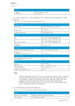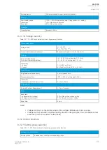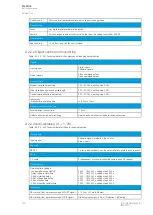
9.2.3.5 Fault locator (21FL)
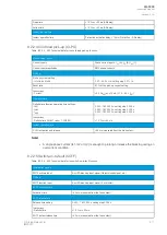
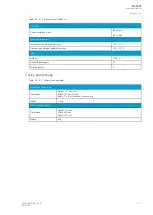
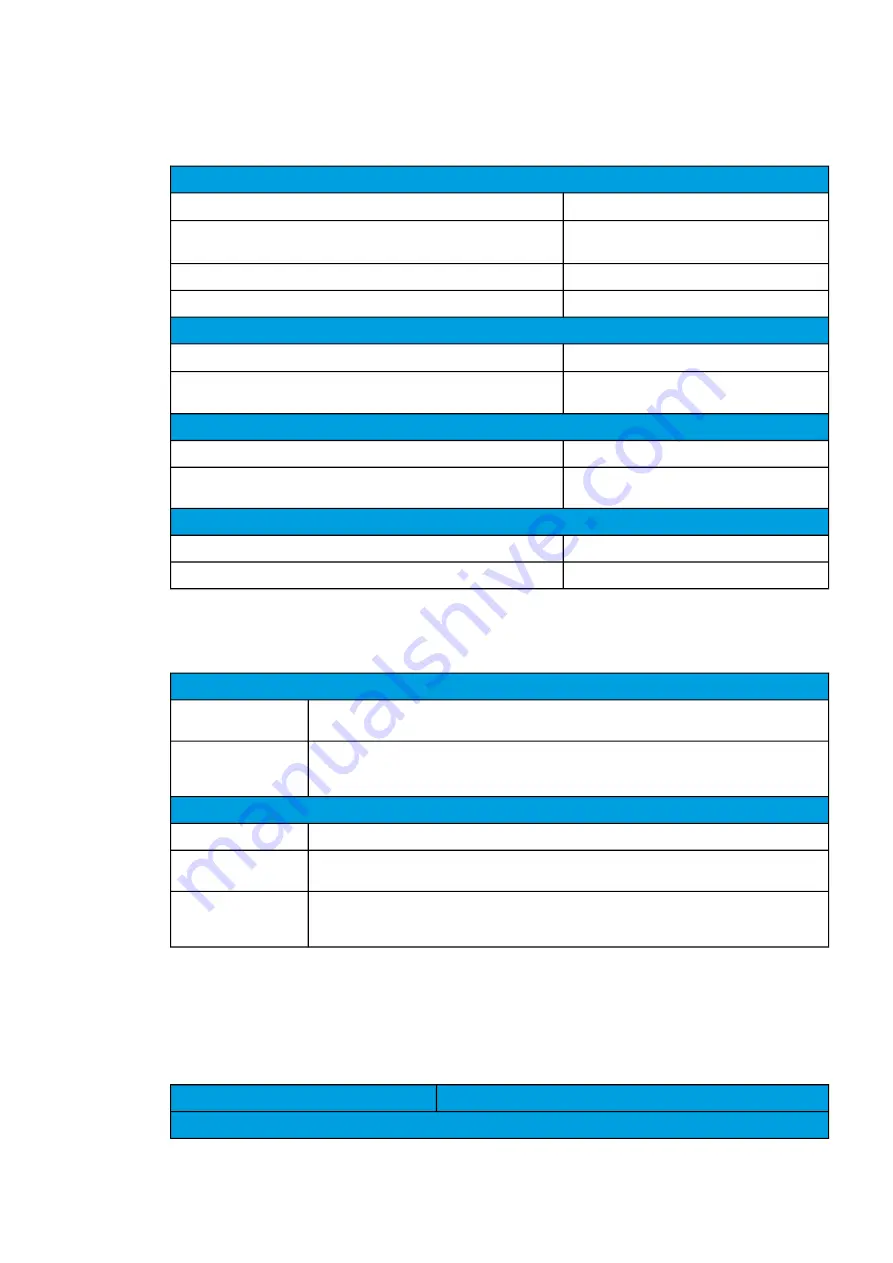
Table. 9.2.3.5 - 310. Technical data for the fault locator function.
Input signals
Current inputs
Phase current inputs: I
L1
(A), I
L2
(B), I
L3
(C)
Voltage inputs
U
L1
, U
L2
, U
L3
U
L12
, U
L23
, U
L31
+ U
0
Calculated reactance magnitudes when line-to-neutral voltages available
XL12, XL23, XL31, XL1, XL2, XL3
Calculated reactance magnitudes when line-to-line voltages available
XL12, XL23, XL31
Pick-up
Trigger current >
0.00…40.00 × I
N
, setting step 0.01 × I
N
Inaccuracy:
- Triggering
±0.5 %I
SET
or ±15 mA (0.10…4.0 × I
SET
)
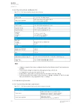
Reactance
Reactance per kilometer
0.000…5.000 s, setting step 0.001
Ω
/km
Inaccuracy:
- Reactance
±5.0 % (typically)
Operation (Triggering)
Activation
From the trip signal of any protection stage
Minimum operation time
At least 0.040 s of stage operation time required
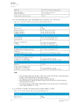
9.2.3.6 Disturbance recorder
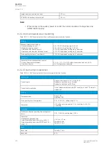
Table. 9.2.3.6 - 311. Technical data for the disturbance recorder function.
Recorded values
Recorder
analog channels
0…20 channels
Freely selectable
Recorder digital
channels
0…95 channels
Freely selectable analog and binary signals
5 ms sample rate (FFT)
Performance
Sample rate
8, 16, 32 or 64 samples/cycle
Recording length
0.000…1800.000 s, setting step 0.001 s
The maximum length is determined by the chosen signals.
Number of recordings
0…100, 60 MB of shared flash memory reserved
The maximum number of recordings according to the chosen signals and operation time setting
combined
9.3 Tests and environmental
Electrical environment compatibility
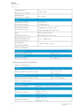
Table. 9.3 - 312. Disturbance tests.
All tests
CE-approved and tested according to EN 60255-26
Emissions
A
AQ
Q-F205
-F205
Instruction manual
Version: 2.04
© Arcteq Relays Ltd
IM00013
415
Summary of Contents for AQ F205
Page 1: ...AQ F205 Feeder protection IED Instruction manual ...
Page 2: ......

