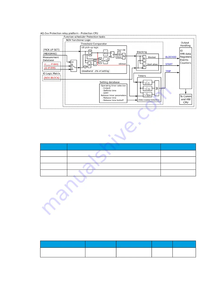
Figure. 5.3.13 - 137. Simplified function block diagram of the U0> function.
Measured input
The function block uses analog voltage measurement values. The function block uses RMS values. A
-20 ms averaged value of the selected magnitude is used for pre-fault data registering.
Table. 5.3.13 - 126. Measurement inputs of the U0> function.
Signal
Description
Time base
U0RMS
RMS measurement of voltage U0/V
5ms
U
L1
RMS
RMS measurement of voltage U
L1
/V
5ms
U
L2
RMS
RMS measurement of voltage U
L2
/V
5ms
U
L3
RMS
RMS measurement of voltage U
L3
/V
5ms
The selection of the AI channel currently in use is made with a setting parameter. In all possible input
channel variations the pre-fault condition is presented with a 20 ms averaged history value from -20 ms
from a START or TRIP event.
Pick-up
The
U
set
setting parameter controls the pick-up of the U0> function. This defines the maximum allowed
measured voltage before action from the function. The function constantly calculates the ratio
between the
U
set
and the measured magnitude (
U
m
) for neutral voltage. The reset ratio of 97 % is built
into the function and is always relative to the
U
set
value. The setting value is common for all measured
amplitudes, and when the
U
m
exceeds the
U
set
value it triggers the pick-up operation of the function.
Table. 5.3.13 - 127. Pick-up settings.
Name
Description
Range
Step
Default
Pick-up setting U0set>
Pick-up setting
1.00…99.00%U
n
0.01%U
n
20.00%U
n
The pick-up activation of the function is not directly equal to the START signal generation of the
function. The START signal is allowed if the blocking condition is not active.
A
AQ
Q-F215
-F215
Instruction manual
Version: 2.04
195


