The function outputs the START, TRIP and BLOCKED signals which can be used for direct I/O
controlling and user logic programming. The function generates general time-stamped ON/OFF events
to the common event buffer from each of the three (3) output signals. In the instant operating mode the
function outputs START and TRIP events simultaneously with an equivalent time stamp. The time stamp
resolution is 1 ms. The function also provides a resettable cumulative counter for the START, TRIP and
BLOCKED events.
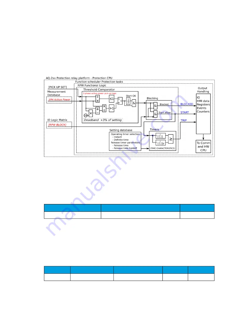
The following figure presents a simplified function block diagram of the reverse power function.
Figure. 5.3.19 - 156. Simplified function block diagram of the Pr function.
Measured input
The function block uses three-phase active power values. A -20 ms averaged value of the selected
magnitude is used for pre-fault data registering. If the protection relay has more than one CT module,
the parameter
Measured side determines which current measurement is used for the power
measurement.
Table. 5.3.19 - 160. Measurement inputs of the Pr function.
Signal
Description
Time base
3PH Active power (P)
Total three-phase active power
5ms
Pick-up
The
P
set
rev.setting parameter controls the pick-up of the Pr function. This defines the maximum
allowed measured three-phase active power before action from the function. The function constantly
calculates the ratio between the
P
set
rev. and the measured magnitude (P
m
). The reset ratio of 97 % is
built into the function and is always relative to the
P
set
rev. value.
Table. 5.3.19 - 161. Pick-up settings.
Name
Description
Range
Step
Default
P
set
rev.
Pick-up setting
0.0…100 000kW
0.01kW
100kW
The pick-up activation of the function is not directly equal to the START signal generation of the
function. The START signal is allowed if the blocking condition is not active.
A
AQ
Q-F215
-F215
Instruction manual
Version: 2.04
226