


Pick-up
The
Iv1, Iv2, Ux1, Ux2 setting parameters and the positive sequence voltage measurement control the
pick-up level of the voltage-restrained overcurrent protection function. The pick-up level defines the
maximum allowed measured current before action from the function. The function constantly calculates
the ratio between the current pick-up level and the measured magnitude (
I
m
) for each of the three
phases. The reset ratio of 97 % is built into the function and is always relative to the current pick-up
value.
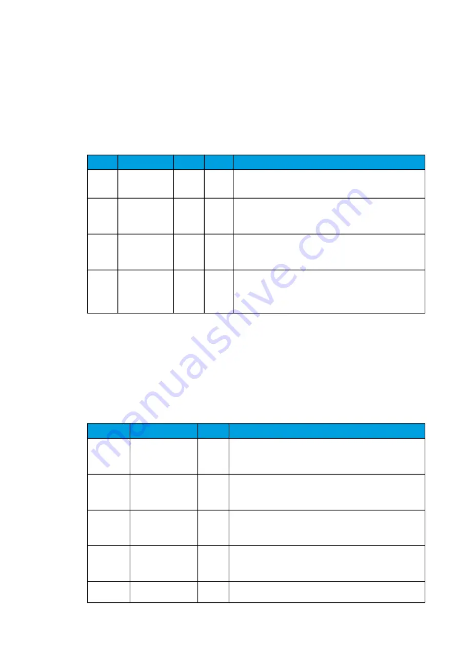
Table. 5.3.20 - 166. Pick-up settings.
Name
Range
Step
Default
Description
1st knee
point
(Iv>)
0.10…40.00xI
n
0.01xI
n
0.2 xI
n
The lower current limit.
2nd
knee
point
(Iv2>)
0.10…40.00xI
n
0.01xI
n
1.2xI
n
The higher current limit.
1st knee
point
voltage
(Ux1)
0.00…150.00%U
n
0.01%U
n
20%U
n
The lower voltage limit.
2nd
knee
point
voltage
(Ux2)
0.00…150.00%U
n
0.01%U
n
100%U
n
The higher voltage limit.
When this value is higher than Ux1, the function operates as voltage-
restrained overcurrent protection. If the two values are equal, the
function operates as voltage-controlled overcurrent protection.
The pick-up activation of the function is not directly equal to the START signal generation of the
function. The START signal is allowed if the blocking condition is not active.
Read-only parameters
The relay's
Info page displays useful, real-time information on the state of the protection function. It is
accessed either through the relay's HMI display, or through the setting tool software when it is
connected to the relay and its Live Edit mode is active.
Table. 5.3.20 - 167. Information displayed by the function.
Name
Range
Step
Description
Iv> condition
0: Normal
1: Start
2: Trip
3: Blocked
-
Displays status of the protection function.
Expected
operating
time
0.000...1800.000s
0.005s
Displays the expected operating time when a fault occurs. When IDMT
mode is used, the expected operating time depends on the measured
highest phase current value. If the measured current changes during a
fault, the expected operating time changes accordingly.
Time
remaining to
trip
-1800.000...1800.000s 0.005s
When the function has detected a fault and counts down time towards a
trip, this displays how much time is left before tripping occurs.
Voltage
measurement
0: Invalid U1 not avail.
1: Ok
-
If phase voltages are not available the function is not able to calculate
positive sequence voltage (U1). This can happen when voltage
measurement mode has been set to "3LL+U4" or "2LL+U3+U4" mode
but none of the channels have been set to "U0" mode.
I> pick-up
level now
0.00...1250.00xIn
0.01xIn
Overcurrent pick-up level used by the function at the moment. The pick-
up level changes with positive sequence voltage setting changes.
A
AQ
Q-F215
-F215
Instruction manual
Version: 2.04
230


