


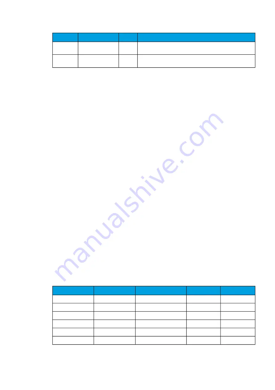
Name
Range
Step
Description
Measured
voltage now
0.00...1250.00%Un
0.01%Un Calculated positive sequence voltage at the moment. This influences
the overcurrent pick-up level used by the function.
I
meas
/I
set
at
the moment
0.00...1250.00
0.01
The ratio between the highest measured phase current and the pick-up
value.
Function blocking
The block signal is checked in the beginning of each program cycle. The blocking signal is received
from the blocking matrix in the function's dedicated input. If the blocking signal is not activated when
the pick-up element activates, a START signal is generated and the function proceeds to the time
characteristics calculation.
If the blocking signal is active when the pick-up element activates, a BLOCKED signal is generated and
the function does not process the situation further. If the START function has been activated before the
blocking signal, it resets and processes the release time characteristics similarly to when the pick-up
signal is reset.
The blocking of the function causes an HMI display event and a time-stamped blocking event with
information of the startup voltage values and its fault type to be issued.
The blocking signal can also be tested in the commissioning phase by a software switch signal when
the relay's testing mode "Enable stage forcing" is activated (
General
→
Device).
The variables the user can set are binary signals from the system. The blocking signal needs to reach
the device minimum of 5 ms before the set operating delay has passed in order for the blocking to
activate in time.
Operating time characteristics for trip and reset
This function supports definite time delay (DT) and inverse definite minimum time delay (IDMT). For
detailed information on these delay types please refer to the chapter "General properties of a protection
function" and its section "Operating time characteristics for trip and reset".
Events and registers
The voltage-restrained overcurrent protection function (abbreviated "VOC" in event block names)
generates events and registers from the status changes in START, TRIP and BLOCKED. The user can
select which event messages are stored in the main event buffer: ON, OFF, or both.
The events triggered by the function are recorded with a time stamp and with process data values.
Table. 5.3.20 - 168. Event codes.
Event number
Event channel
Event block name
Event code
Description
7168
112
VOC1
0
Start ON
7169
112
VOC1
1
Start OFF
7170
112
VOC1
2
Trip ON
7171
112
VOC1
3
Trip OFF
7172
112
VOC1
4
Block ON
7173
112
VOC1
5
Block OFF
A
AQ
Q-F215
-F215
Instruction manual
Version: 2.04
231


