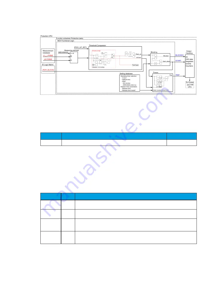
Figure. 5.4.13. - 80. Simpli ed function block diagram of the NOV function.
Measured input values
Function block uses the analog voltage measurement values. Function block utilizes fundamental
frequency RMS values. -20ms averaged value of the selected magnitude is used for pre-fault data
registering.
Table. 5.4.13. - 124. Analogic magnitude used by the NOV function.
Signal
Description
Time base
U0RMS
Fundamental RMS measurement of voltage U0/V
5 ms
Selection of the used AI channel is made with a setting parameter. In all possible input channel
variations pre-fault condition is presented with 20 ms averaged history value from -20 ms of Start or
Trip event.
Real-time info displayed by the function
The relays Info-page displays useful information in real time of the state of the protection function either
through relays HMI display or with AQtivate software when connection there is a connection to relay
and Live Edit-mode is activated.
Name
Unit
Description
U0> Pick-up
setting
V
Primary voltage required for tripping. The displayed pick-up voltage level depends on the chosen
U0 measurement input selection, pick-up setting and the voltage transformer settings.
Expected
operating time s
Displays the expected operating time in case a fault occurs
Time
remaining to
trip
s
When the relay has picked up and is counting time towards pick-up
Umeas/Uset
at the
moment
Um/Uset Ratio between measured/calculated neutral voltage and the pick-up value.
General settings
The following general settings de ne the general behavior of the function. These settings are static i.e.
it is not possible change them with setting group switching.
AQ-F255
Instruction manual
Version: 2.00
© Arcteq Relays Ltd
136


