4. IED user interface
4.1. Panel structure
AQ 200 series IED user interface section is divided into hardware- and software user interface
sections. Software interface is divided into local panel con guration and programming by using
AQtivate 200 freeware software suite.
4.1.1. AQ 250 series local panel structure
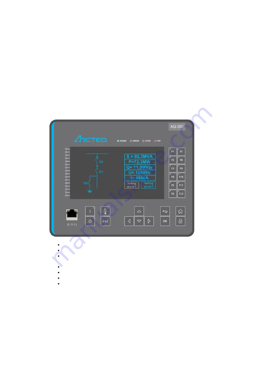
AQ 200 series IED have multiple LEDs, control buttons, function buttons and local RJ-45 Ethernet port
for con guration on front as a default. On rear each unit is equipped with RS-485 serial interface and
RJ-45 Ethernet interface options as a standard. See list below.
Figure. 4.1.1. - 1. Local panel structure.
4 default LEDs for free con guration: Power, Error, Start and Trip.
16 freely con gurable LEDs with programmable legend texts.
3 object control buttons: Choose the controllable object with Ctrl –button, control breaker with
0- and I push buttons.
L/R push button for local remote control.
7 Navigation buttons for IED local programming and a button for password activation.
12 freely con gurable function buttons.
RJ-45 Ethernet port for IED con guration.
Used views are freely con gurable with buttons for changing settings groups or controlling the relays
logic in general. Object status (Circuit breaker/Disconnector) can be displayed on the screen. All
measured and calculated values (currents, voltages, power, energy, frequency etc.) can be shown in
the screen.
AQ-F255
Instruction manual
Version: 2.00
9
© Arcteq Relays Ltd


