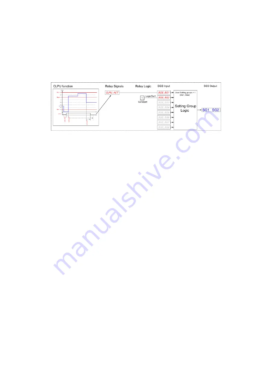
As can be seen from these presented examples the setting group selection with application control has
to be built fully when using this approach for the setting group control. Setting group will not change
back to SG1 if it is not controlled back to SG1 by the application. This explains the inverted signal
“NOT” and use of logics in the SG control. Another approach can be that the SG2 in these cases
would be selected as primary SG while with “On” signal would be controlled higher priority SG1. By this
way after the automatic control is over SG would return automatically to SG2.
Figure. 5.5.1. - 120. Example of setting default SG constant signal.
5.5.2. Object control and monitoring (OBJ)
Object control and monitoring function takes care of circuit breaker and disconnector controlling and
status monitoring. Monitor and control is based on the statuses of the IED binary inputs and outputs
con gured. In the relay the amount of controllable and monitored objects is dependent of available IO.
One controllable object requires minimum of 2 output contacts. For status monitoring typically 2 binary
inputs are utilized per monitored object. Alternatively, object status monitoring can be performed with
single digital input using rising and falling edge monitoring and logic virtual inputs.
Object can be controlled from local control, remote control and HMI mimic manually or by software
function automatically. For remote control from protocols the modes “Direct Control” and “Select
before Execute” are dealt in the protocol handling itself.
Object control consists of control logic, control monitor and output handler. In addition of these main
parts in the object control block can be added object related CBFP and object wear monitor. For the
basic version of the object control block these additional functions are not included.
Outputs of the function are Object open and Object close control signals. In addition to these output
controls the function will report the monitored object status and applied operations. Setting parameters
are static inputs for the function which are changed only by user input in the setup phase of the
function.
Inputs for the function are binary status indications open and close control signals, blockings, object
ready and synchrocheck monitor signals. The function registers its operation into 12 last time-stamped
registers and also generates general time stamped ON/OFF events to the common event buffer from
each of the two output signal as well as several operational event signals. Time stamp resolution is
1ms. Function provides also cumulative counters for Open and Close act and Open / Close Failed
events.
In the following gure is presented the simpli ed function block diagram of the OBJ function.
AQ-F255
Instruction manual
Version: 2.00
211
© Arcteq Relays Ltd


