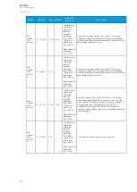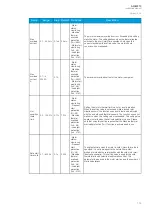
Event number
Event channel
Event block name
Event code
Description
3843
60
NUC1
3
Trip OFF
3844
60
NUC1
4
Block ON
3845
60
NUC1
5
Block OFF
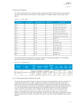
The function registers its operation into the last twelve (12) time-stamped registers. The register of the
function records the ON event process data for START, TRIP or BLOCKED. The table below
presents the structure of the function's register content.
Table. 5.3.11 - 84. Register content.
Date and
time
Event
code
Fault type
Trigger
current
Fault
current
Prefault
current
Trip time
remaining
Used SG
dd.mm.yyyy
hh:mm:ss.mss
3840-3845
Descr.
L1-G…L1-L2-L3
Start
average
current
Trip -20ms
averages
Start -200ms
averages
0
ms...1800s
Setting group
1...8 active
5.3.12 Mechanical jam protection (Im>; 51M)
The mechanical jam protection function is used for monitoring motor loading after motor starting. When
a motor-run apparatus jams during its work load, this function can be used to disconnect the motor
from the feeding network in order to avoid further damage to the motor drive. The function is active
only after the motor has started, and it is blocked during motor starting. This is done through
an internal connection of
Motor running and through a Motor starting signal taken from the Motor
status monitoring function. This function operates similarly to the motor starting/locked rotor function
(Ist>; 48/14) although it operates on Definite Time delay and does not work during motor starting. Also,
with the help of a dedicated locked rotor function and mechanical jam protection the user can divide all
possible fault situations based on a quick definition of the fault types in relay events. Additionally, the
Ist> function's setup can be problematic with heavy inertia loads that experience a locked rotor
situation during work load. Having separate functions for start-up and for mechanical jams divides the
situations clearly; for example, the mechanical jam protection can be set to instant operation while the
locked rotor function allows motor starting several tens of seconds.
The outputs of the function are the START, TRIP and BLOCKED signals. The load jam protection
function uses a total of eight (8) separate setting groups which can be selected from one common
source.
The function can operate on instant or time-delayed mode. In the time-delayed mode the operation can
be set to definite time (DT) delay.
The inputs for the function are the following:
• setting parameters
• digital inputs and logic signals
• measured and pre-processed current magnitudes.
The function outputs the START, TRIP and BLOCKED signals which can be used for direct I/O
controlling and user logic programming. The function generates general time-stamped ON/OFF events
to the common event buffer from each of the three (3) output signals. In the instant operating mode the
function outputs START and TRIP events simultaneously with an equivalent time stamp. The time stamp
resolution is 1 ms. The function also provides a cumulative counter for the START, TRIP and BLOCKED
events.
The following figure presents a simplified function block diagram of the load jam protection function.
A
AQ
Q-M210
-M210
Instruction manual
Version: 2.04
154


