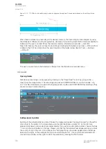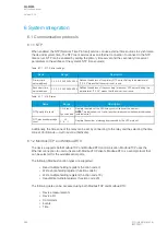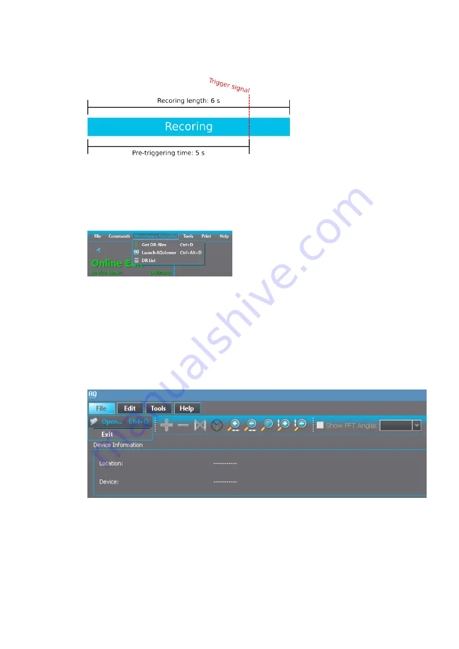
Figure. 5.5.5 - 177. Effects of recording length and pre-triggering time signals. This example is based on the settings shown
above.
When there is at least one recording in the device's memory, that recording can be analyzed by using
the AQviewer software (see the image below). However, the recording must first be made accessible to
AQViewer. The user can read it from the device's memory (
Disturbance recorder
→
Get DR-
files). Alternatively, the user can load the recordings individually (Disturbance recorder
→
DR List) from
a folder in the PC's hard disk drive; the exact location of the folder is described in
Tools
→
Settings
→
DR path.
The user can also launch the AQviewer software from the
Disturbance recorder menu.
AQviewer
Opening f
Opening folders
olders
Disturbance recordings can be opened by clicking on the "Open folder" icon or by going to
File
→
Open (see the image below). The recordings are packed COMTRADE files; a -zip file includes *.cfg
and *.dat files. AQviewer can open both original packed .zip files and COMTRADE files directly as they
are are located in same directory.
A
Adding signals t
dding signals to plo
o plotttters
ers
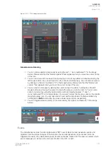
By default, the default plotter is empty. Choose the measured signals ("Analog channels") on the left to
move them to the plotter. In the image below (on the left) the phase currents IL1, IL2 and IL3 are
selected; AQViewer color-codes them automatically. If you want to add another plotter, choose the blue
"+" icon (in the main toolbar on the top). Please note that the "Add plotter" text appears when you move
the cursor on top of the icon. Once clicked, the "Add graph" pop-up window appears (see the image
below on the right). In the example the line-to-neutral voltages UL1, UL2 and UL3 are selected and
moved to the window on the right. Confirm the selection by clicking the "OK" button.
A
AQ
Q-M255
-M255
Instruction manual
Version: 2.06
350
© Arcteq Relays Ltd
IM00020
Summary of Contents for AQ-M255
Page 1: ...AQ M255 Motor protection IED Instruction manual...
Page 2: ......

