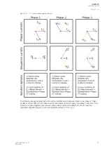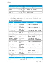
Problem
Check / Resolution
The measured
voltage amplitudes are OK
but the angles are
strange./
The voltage unbalance
protection trips
immediately after
activation./
The earth fault protection
trips immediately after it is
activated and voltage
calculated.
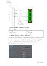
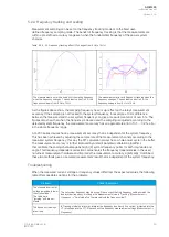
The voltages are connected to the measurement module but the order or polarity of one or all
phases is incorrect. In relay settings, go to
Measurement
→
Phasors and check the "System
voltage vectors" diagram. When all connections are correct, the diagram (symmetric feeding)
should look like this:
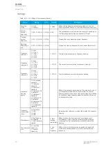
Settings
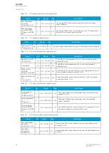
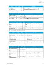
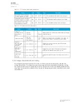
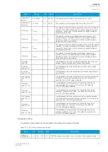
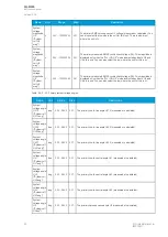
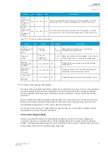
Table. 5.2.2 - 24. Settings of the VT scaling.
Name
Range
Step
Default
Description
Voltage
measurement
mode
0: 3LN+U4
1: 3LL+U4
2: 2LL+U3+U4
-
0:
3LN+U4
The relay's voltage wiring method. The voltages are scaled according
the set voltage measurement mode.
U3 mode U0
or SS
0: Not Used
1: U0
2: SS
-
0: Not
Used
The voltage channel U3 can be used to measure zero sequence
voltage (U0) or the Synchrocheck voltage (SS). If neither is needed,
the (default) option "Not Used" should be active. This setting is only
valid if the "2LL+U3+U4" mode is selected.
U0 (U3)
Measured
from
0: Broken Delta
1: Neutral point
2: Open delta
-
0: Broken
delta
Defines how the secondary voltage is scaled to the primary. Does not
affect how protection operates, it only affects the displayed primary
voltages. This parameter is visible when the "U3 mode U0 or SS" has
been set to the "U0" mode.
U4 mode U0
or SS
0: Not Used
1: U0
2: SS
-
0: Not
Used
The voltage channel U4 can be used to measure zero sequence
voltage (U0) or the Synchrocheck voltage (SS). If neither is needed,
the (default) option "Not Used" should be active.
U0 (U4)
Measured
from
0: Broken Delta
1: Neutral point
2: Open delta
-
0: Broken
delta
Defines how the secondary voltage is scaled to the primary. Does not
affect how protection operates, it only affects the displayed primary
voltages. This parameter is visible when the "U4 mode U0 or SS" has
been set to the "U0" mode.
Voltage
memory
0: Disabled
1: Activated
-
0:
Disabled
Activates the voltage memory. The "Voltage memory" chapter
describes the function in more detail.
P-E Voltage
measurements
0: No P-E
voltages
available
1: P-E Voltages
calculated
2: P-E Voltages
measured
-
-
Indicates whether or not phase-to-earth voltages are available. Also
indicates whether P-E voltages are measured from the voltage
channels directly or if they are calculated from measured line-to-line
and zero sequence voltages.
VT primary
1…1000000.0V 0.1V
20000.0V The rated primary voltage of the voltage transformer.
VT secondary
0.2…400.0V
0.1V
100.0V
The rated secondary voltage of the voltage transformer.
U3 Res/SS VT
primary
1…1000000V
0.1V
20000.0V The primary nominal voltage of the connected U0 or SS VT. This
setting is only valid if the "2LL+U3+U4" mode is selected.
U3 Res/SS VT
secondary
0.2…400V
0.1V
100.0V
The secondary nominal voltage of the connected U0 or SS VT. This
setting is only valid if the "2LL+U3+U4" mode is selected.
A
AQ
Q-M255
-M255
Instruction manual
Version: 2.06
36
© Arcteq Relays Ltd
IM00020
Summary of Contents for AQ-M255
Page 1: ...AQ M255 Motor protection IED Instruction manual...
Page 2: ......


