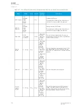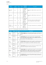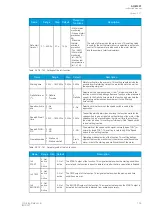
Name
Range
Step
Default
Protection
functions
Description
Starts when
cold
1…100
1
3
- Motor status
monitoring
- Frequent
start
protection
(N>; 48)
The number of allowed starts per x hours for a cold
motor.
Starts when
hot
1…100
1
2
- Motor status
monitoring
- Frequent
start
protection
(N>; 48)
The number of allowed starts per x hours for a hot
motor.
Starts in hours 1…100h
1h
1h
- Motor status
monitoring
- Frequent
start
protection
(N>; 48)
The number of hours when the parameters of the
number of allowed starts (hot and cold) apply.
Min time
between starts 0.1…600.0s
0.1s
20.0s
- Motor status
monitoring
- Frequent
start
protection
(N>; 48)
The minimum time between starts or start attempts.
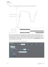
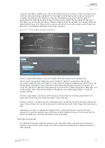
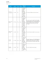
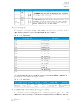
Table. 5.4.17 - 157. Output signals of the motor status monitoring function.
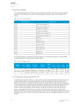
Name
Range Step Default
Description
Motor
stopped
0: Not
active
1:
Active
-
0: Not
active
The
Mo
Mottor st
or stopped
opped signal is active when the function detects a current below the
set value of "No load current". This signal presents a situation when a motor is not
running.
Motor
starting
0: Not
active
1:
Active
-
0: Not
active
The
Mo
Mottor star
or starting
ting signal is active when a motor start-up is detected. In DOL
mode, the signal is active when the measured current exceeds the "Start detect
current" (from the Motor stopped situation); the signal deactivates when the current
decreases below the "Max overloading current".
Motor
running
0: Not
active
1:
Active
-
0: Not
active
The
Mo
Mottor running
or running signal is active when the measured current is above the set "No
load current" (as long as the Motor starting situation has passed). This signal is
released when the measured current is below the "No load current" setting.
Motor
stalled
0: Not
active
1:
Active
-
0: Not
active
The
Mo
Mottor stalled
or stalled signal is active when the measured current exceeds the "Max
overload current" setting (from the Motor running situation).
Missing
phase
0: Not
active
1:
Active
-
0: Not
active
The
Missing pha
Missing phase
se signal is activated when the measured current of one phase is
below the "No load current" setting, and the measured currents of two phases are
above the "Min locked rotor current" setting. This signal can be used for quickly
halting the motor's start-up if one phase is lost and the motor cannot start.
Load
Normal
0: Not
active
1:
Active
-
0: Not
active
The
LLoad normal
oad normal signal is active when the measured current is above the set "No
load current" and below the motor's nominal current (including the ambient and
service factor corrections).
A
AQ
Q-M257
-M257
Instruction manual
Version: 2.07
188
© Arcteq Relays Ltd
IM00021
Summary of Contents for AQ-M257
Page 1: ...AQ M257 Motor protection IED Instruction manual...
Page 2: ......


