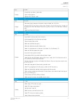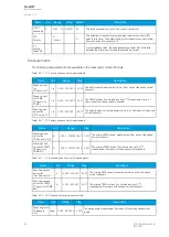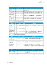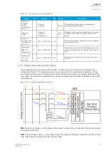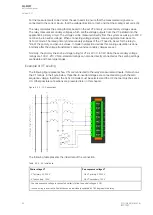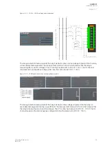
Table. 5.2.1 - 6. Initial data.
Hig
High-v
h-volta
oltage side C
ge side CTT
- CT primary: 800 A
- CT secondary: 1 A
Hig
High-v
h-volta
oltage side nominal curr
ge side nominal current
ent
669 A
R
Ring cor
ing core C
e CT in Input I02
T in Input I02
- 3I0CT primary: 250 A
- 3I0CT secondary: 1 A
LLoow
w-v
-volta
oltage side C
ge side CTT
- CT primary: 8000 A
- CT secondary: 1 A
LLoow
w-v
-volta
oltage side nominal curr
ge side nominal current
ent
5888 A
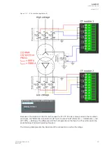
- both CTs are pointing through the transformer (HV-S2 and LV-S2 are pointing in the same direction)
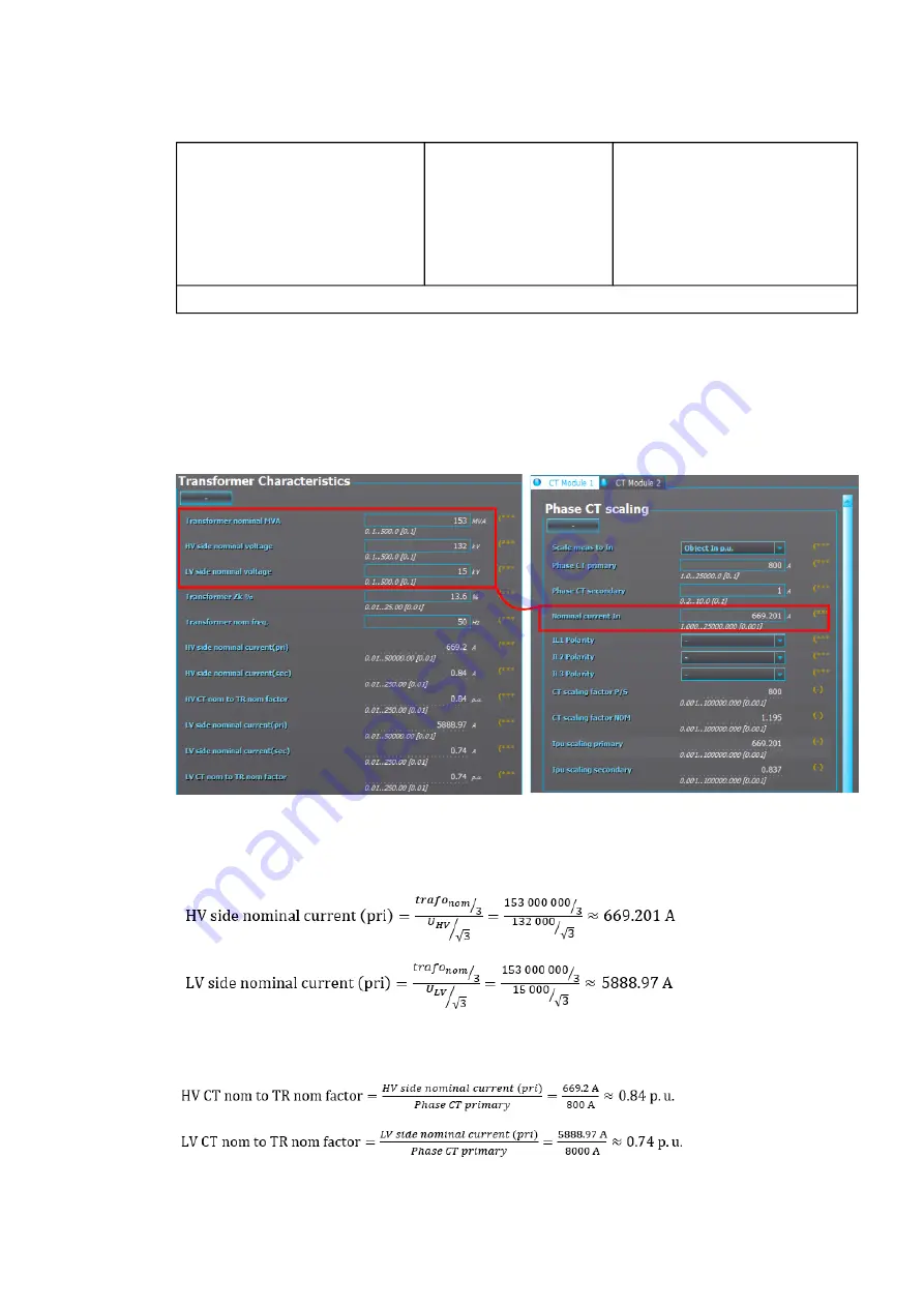
The nominal current for both the HV and LV sides of the protected transformer are calculated based on
the values set in the
Transformer characteristics menu (Protection
→
TrafoModule
→
TSTAT
→
INFO).
The ratio between the CT modules 1 and 2 can be set in their respective tabs at
Measurement
→
Transformers. The per-unit scaling ("Scale meas. to In") is automatically set to "Object in p.u." in all
machine protection relays and it cannot be changed.
Figure. 5.2.1 - 5. Phase CT scaling to machine nominal.
As seen in the image above, relay calculates both the HV side nominal current (669.2 A) and the LV
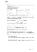
side nominal current (5 888.97 A). The nominal current calculations are done according to the
following formulas:
The HV and LV side nominal current can also be calculated in per unit values as follows:
A
AQ
Q-M257
-M257
Instruction manual
Version: 2.07
© Arcteq Relays Ltd
IM00021
23
Summary of Contents for AQ-M257
Page 1: ...AQ M257 Motor protection IED Instruction manual...
Page 2: ......

