Name
Range
Step
Default
Prot.funcs.
Description
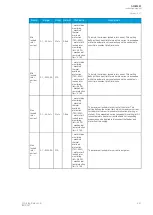
Hot
condition
theta
limit
0.0…100.0%
0.1%
70%
- motor status
monitoring
- frequent start
protection (N>)
- machine
thermal
overload
protection
(TM>; 49M)
- motor start/
locked rotor
monitoring
(Ist>; 48/14)
- mechanical
jam protection
(Im>; 51M)
Setting the thermal limit for a hot motor and a cold motor.
When this setting value is not exceeded while a locked
rotor situation occurs, the function uses a cold stall curve
adjusted with the actually used thermal capacity. The
function uses a hot stall curve when this setting value is
exceeded. This also applies to starts when the motor is hot
or cold. Please note that using this setting requires that the
Machine thermal overload protection (TM>) function is
activated and in use.
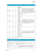
Safe stall
time cold 0.1…600.0s
0.1s
20.0s
- motor status
monitoring
- machine
thermal
overload
protection
(TM>; 49M)
- motor start/
locked rotor
monitoring
(Ist>; 48/14)
- mechanical
jam protection
(Im>; 51M)
- frequent start
protection (N>;
66)
The safe stall time when the motor is cold. Unless this
value is specified, it is set to be equal to the hot stall time.
Most probably this leads to overprotection with the cold
motor stall (best case scenario). This setting value is used
for the cold thermal stall curve selection in automatic
control. This parameter is also used in the motor start-up
and the number of starts calculations.
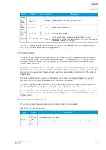
Safe stall
time hot
0.1…600.0s
0.1s
15.0s
- motor status
monitoring
- machine
thermal
overload
protection
(TM>; 49M)
- Motor start/
locked
rotor monitoring
(Ist>; 48/14)
- mechanical
jam protection
(Im>; 51M)
- frequent start
protection (N>;
66)
The safe stall time when the motor is hot. This setting value
is used for the hot thermal stall curve selection in automatic
control. This parameter is also used in the motor start-up
and the number of starts calculations.
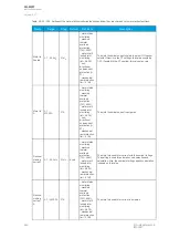
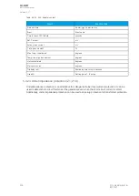
Table. 5.4.23 - 195. Motor's thermal image settings.
Name
Range
Step
Default
Description
Pick-up
current
0.00…40.00xI
n
0.01xI
n
1.00xI
n
The current for 100 % thermal capacity to be used (the pick-up current in
p.u., this current
t
max
achieved in
t x 5).
NPS-
biasing in
use
0: No NPS-
biasing
1: NPS-biasing
in use
-
0: No
NPS-
biasing
in use
The selection of whether or not the thermal replica reference current is
biased with the NPS current.
NPS-bias
factor
0.1…10.0
0.1
3.0
The negative sequence current biasing factor. This factor depends on the
motor's construction and is in relation to the positive and negative
sequence rotor resistances. A typical value for this is the default setting
3.0.
A
AQ
Q-M257
-M257
Instruction manual
Version: 2.07
© Arcteq Relays Ltd
IM00021
249
Summary of Contents for AQ-M257
Page 1: ...AQ M257 Motor protection IED Instruction manual...
Page 2: ......


