Pick-up
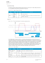
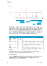
Figure. 5.4.26 - 138. Operating characteristics of inadvertent energizing protection.
The
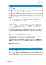
Voltage limit U< and Current limit I>/< activation setting parameter controls the the pick-up of
the function. Whenever the measured voltage is under the
Voltage limit U< setting value the function is
"Started". If voltage rises over the setting limit the function will wait for the duration set to
Time delay for
releasing start condition before releasing the start condition. When voltage decreases under Voltage
limit U< the function will wait until duration set to Time delay for U< activation has passed. If the
measured current rises over
Current limit I>/< activation parameter while voltage is under the Voltage
limit U< parameter the function will trip. Keep in mind that even if voltage is over the set limit the
function can trip form rising current if start release time delay is still counting down.
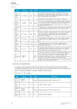
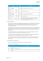
Table. 5.4.26 - 217. Pick-up settings.
Name
Range
Step Default
Description
Voltage
limit U<
0.00...99.00
%Un
0.01
%Un
50.00
%Un
Sets the under voltage limit for the function.
Time
delay for
U<
activation
0.000...1800.000
s
0.005
s
5.000 s
When the voltage drops under the
Voltage limit U< setting the function will
wait for the duration of this parameter setting to activate "start" condition.
Current
limit I>/<
0.05...3.00 xIn
0.05
xIn
0.05 xIn If "start" condition is on and each phase current is above this limit the
function will trip.
Time
delay for
releasing
start
condition
0.000...1800.000
s
0.005
s
0.250 s
When measured voltage rises over
Voltage limit U< setting the function will
wait for the duration of this parameter setting before disabling start
condition. If each phase current rises over
Current limit I>/< setting while
start release is still going on the function will trip.
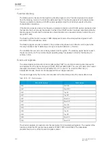
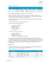
The pick-up activation of the function is not directly equal to the START signal generation of the
function. The START signal is allowed if the blocking condition is not active.
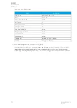
Read-only parameters
The relay's
Info page displays useful, real-time information on the state of the protection function. It is
accessed either through the relay's HMI display, or through the setting tool software when it is
connected to the relay and its Live Edit mode is active.
A
AQ
Q-M257
-M257
Instruction manual
Version: 2.07
266
© Arcteq Relays Ltd
IM00021
Summary of Contents for AQ-M257
Page 1: ...AQ M257 Motor protection IED Instruction manual...
Page 2: ......


