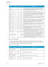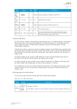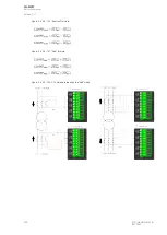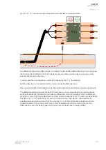
Figure. 5.4.29 - 153. CTs' starpoints requiring the "Subtract" mode.
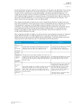
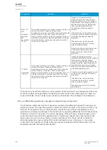
The differential function has two (2) separate stages built into the function. Non-restraint characteristics
use only the "Average mode and Max mode formulas (described below) as the comparison base.
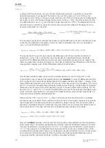
Restraint characteristics also make a so-called bias calculation for each of the phases in order to adjust
the differential stage towards the measured currents. Bias calculation can be sensitive or coarse (see
the following formulas).
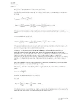
Figure. 5.4.29 - 154. Average mode (sensitive biasing).
Figure. 5.4.29 - 155. Max mode (coarse biasing).
Next, these two formulas are combined in a graph: the x-axis presents the measured differential
current, and the y-axis presents the calculated bias current. The following graph shows the differential
function characteristic, both biased and non-biased.
A
AQ
Q-M257
-M257
Instruction manual
Version: 2.07
© Arcteq Relays Ltd
IM00021
291
Summary of Contents for AQ-M257
Page 1: ...AQ M257 Motor protection IED Instruction manual...
Page 2: ......


