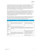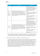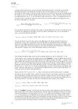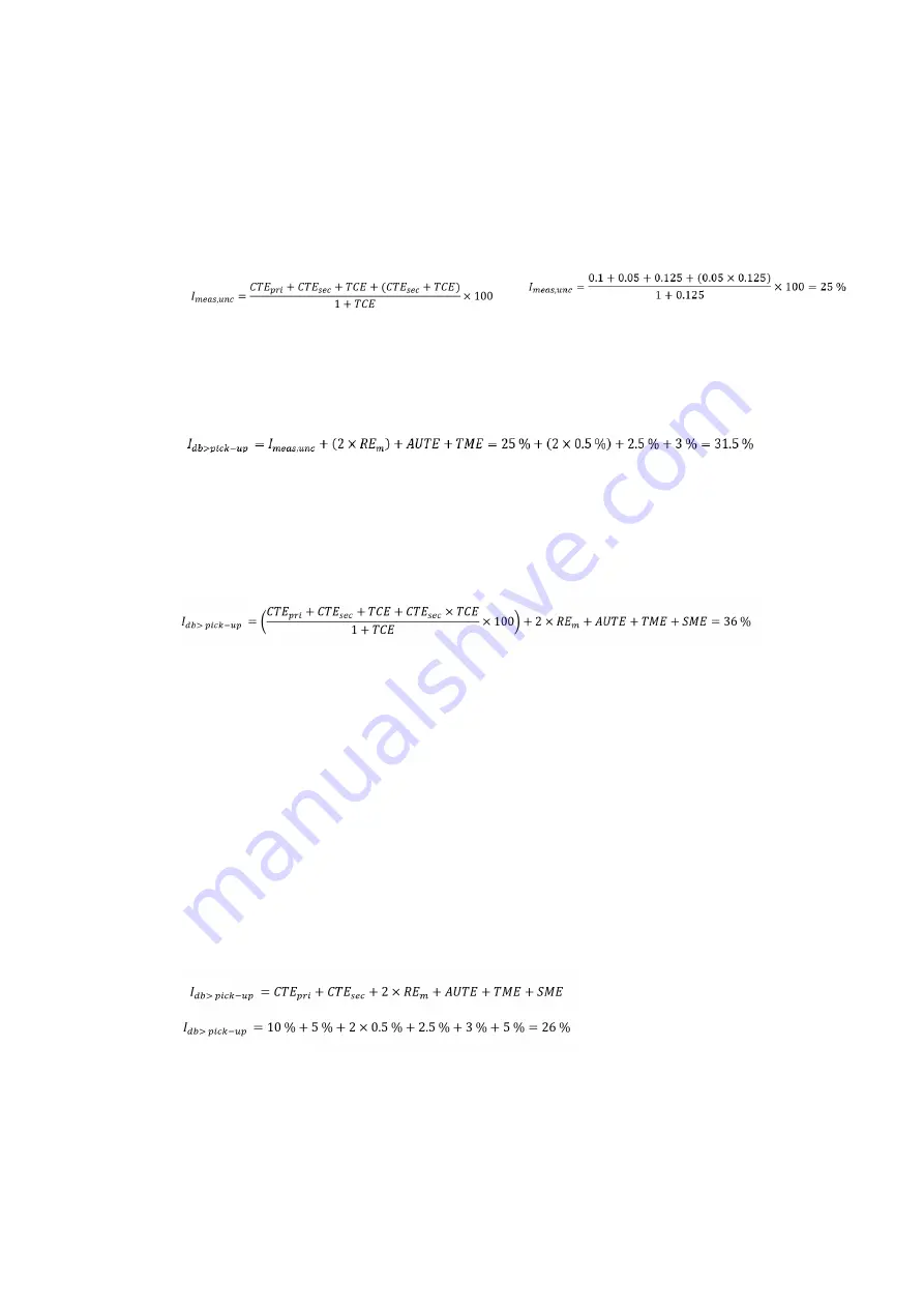
Looking at the formula above, one can see that the absolute maximum uncertainty as well as the
absolute measurement are needed. The former is the sum of the primary CT error (CTE
pri
), the
secondary CT error (CTE
sec
), the tap changer maximum error (TCE) and the product of multiplying the
secondary CT error with the tap changer maximum error (CTE
sec
× TCE). The latter is the sum of the
so-called expected value (1 × I
n
) and the tap changer maximum error (TCE). The images below show
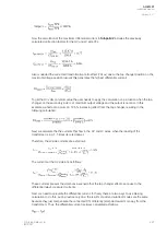
the full formula (on the left) as well as the formula and its result when filled with the figures from our
example configuration (on the right):
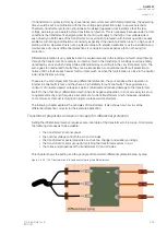
The calculation result (25 %) presents the maximum caused differential current to nominal that can be
caused by the transformer's properties. If we know other uncertainties, they can now be added to
I
meas, unc
to get the following operation:
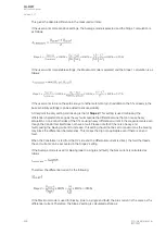
This means that in the worst case scenario, the differential current flows while the transformer's
operation is normal. This is why the final result usually gets an added safety margin: the stable
operation of the differential protection must be ensured and possible calculation errors negated. The
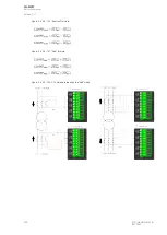
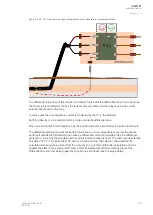
following image shows the base sensitivity (i.e. the minimum setting for the differential current that the
relay operation requires) given to the differential protection characteristics:
Now the base sensitivity takes into account the starting situation (no load to Turnpoint 1) in the
characteristics. Next, it needs to be decided where to set TTurnpoint 1
urnpoint 1. In most of differential relays this
point is either fixed or automatically defined based on the base sensitivity and Slope 1; however, in this
type of differential relay this point can be set by the user. If the user wants a high sensitivity, TP1 can be
set to 1 ×
I
n
since the calculated base sensitivity already factors in the tap changer effect and all other
differential current sources that normal operating causes. If the user prefers coarse settings, TP1 can
be set to 0.5 ×
I
n
, even 0.01 ×
I
n
. The limit is determined by the sum of the protection principle the user
wants. A smaller value results in a conservative and stable operation, while a larger value results in a
highly sensitive but possibly unstable protection.
Please note that if TP 1 is set to 0.01 ×
I
n
, Slope 1 starts directly from the setting and no unbiased
sensitive section is available. This is useful when the user does not want base sensitivity to include the
tap changer effect, but instead have it be accounted for in Slope 1 directly. This can lead to optimal
sensitivity and stable settings for a differential relay even if there are no non-biased sensitive section in
the characteristics. In this case, the formula to calculate the base sensitivity is as follows:
Next are the SSlope 1
lope 1 settings, which present the relay's restrain characteristics over the transformer's
load current range. This slope should be effective up to the maximum transformer loading. This value
for power transformers is usually around 1.0 to 2.0 ×
I
n
; for large power transformer a typical value is
1.5 ×
I
n
. The purpose is to compensate the measurement errors caused by a relatively high current,
including the tap changer effect. Slope 1 is calculated by using the transformer and CT nominal values
in the maximum full load (Turnpoint 2) of the transformer with highest possible differential current
causing tap position. Generally the Slope 1 setting is calculated as follows:
A
AQ
Q-M257
-M257
Instruction manual
Version: 2.07
296
© Arcteq Relays Ltd
IM00021
Summary of Contents for AQ-M257
Page 1: ...AQ M257 Motor protection IED Instruction manual...
Page 2: ......


