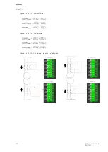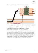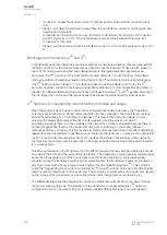
When designing the CTs and their wiring, please keep in mind the following: the resistance of the wire
doubles when the length is doubled, and the resistance halves when the wire's cross-section are
doubles. When 1 A secondary is used (instead of 5 A secondary), all burdens drop to a level smaller to
portion of 5A
2
, e.g. 1/25.
Although copper cables are normally used to connect CTs to a relay, the table below also presents the
resistivity (rho) and conductivity (sigma) properties of aluminum (at +20 ºC):
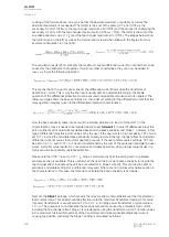
You can use the following formula to calculate the resistivity in temperatures other than +20 ºC:
For example, the resistivity of copper at +75 ºC is calculated like this:
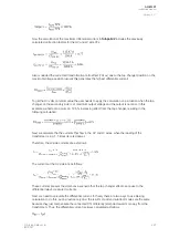
With this value we can calculate the resistances (per meter) of the most commonly used copper wires
given value most common used copper wires at +75 ºC by using the above-mentioned formula for
R
cond
:
Cross-section (mm
2
)
Resistance (
Ω
/m)
1.5
0.0135
2.5
0.00812
4.0
0.00508
6.00
0.00338
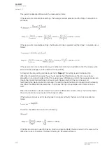
It is recommended that you use the worst-case scenario as the basis for calculating the CT burden. In
most cases these +75 ºC values are sufficient. If the ambient temperature in your application is higher
than +75 ºC, the resistance should be calculated for that specific temperature.
A
AQ
Q-M257
-M257
Instruction manual
Version: 2.07
300
© Arcteq Relays Ltd
IM00021
Summary of Contents for AQ-M257
Page 1: ...AQ M257 Motor protection IED Instruction manual...
Page 2: ......


