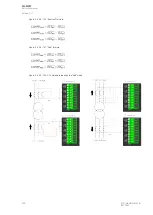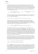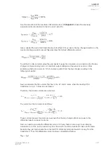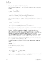
Figure. 5.4.29 - 160. Example differential characteristics
The four characteristics (the image above) present the setting variations based to the Average restraint
calculation mode (figures A and B) and the Maximum restraint calculation modes (figures C and D).
The characteristics are set to be equally sensitive in each of them. You can also see the variations in
Turnpoint 1 settings: in Figures A and C it is set at 1.0 ×
I
n
, whereas in Figures B and D it is set
at 0.01 ×
I
n
.
Zero sequence compensation for external earth faults
Our example presented only one type of transformer and its properties. Another very common variation
is the type of transformer where the star side (HV, LV, or both) is earthed and thus forms a route
outside the differential zone (see the image below).
A
AQ
Q-M257
-M257
Instruction manual
Version: 2.07
304
© Arcteq Relays Ltd
IM00021
Summary of Contents for AQ-M257
Page 1: ...AQ M257 Motor protection IED Instruction manual...
Page 2: ......

