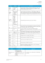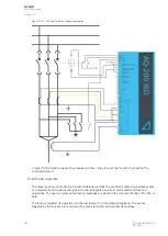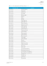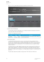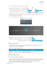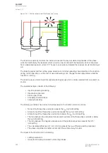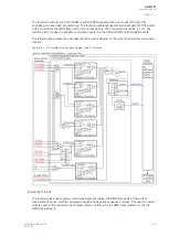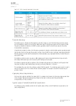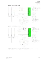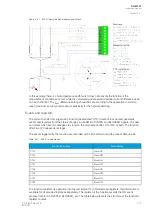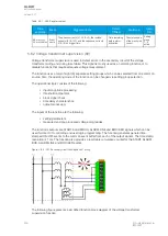
Figure. 5.5.8 - 187. Logic output example. Logical output is connected to an output relay in matrix.
Logical output descriptions
Logical outputs can be given a description. The user defined description are displayed in most of the
menus (logic editor, matrix, block settings etc.).
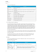
Table. 5.5.8 - 278. Logical output user description.
Name
Range
Default
Description
User editable
description LOx
1...31
characters
Logical
output x
Description of the logical output. This description is used in several menu
types for easier identification.
5.5.9 Logical inputs
Logical inputs are binary signals that a user can control manually to change the behavior of the
AQ-200 unit or to give direct control commands. Logical inputs can be controlled with a virtual switch
built in the mimic and from a SCADA system (IEC 61850, Modbus, IEC 101, etc.). Logical inputs are
volatile signals: their status will always return to "0" when the AQ-200 device is rebooted. 32 logical
inputs are available.
Logical inputs have two modes available: Hold and Pulse. When a logical input which has been set to
"Hold" mode is controlled to "1", the input will switch to status "1" and it stays in that status until it is
given a control command to go to status "0" or until the device is rebooted. When a logical input which
has been set to "Pulse" mode is controlled to "1", the input will switch to status "1" and return back to "0"
after 5 ms.
The figure below presents the operation of a logical input in Hold mode and in Pulse mode.
A
AQ
Q-M257
-M257
Instruction manual
Version: 2.07
364
© Arcteq Relays Ltd
IM00021
Summary of Contents for AQ-M257
Page 1: ...AQ M257 Motor protection IED Instruction manual...
Page 2: ......


