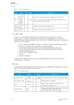
Name
Range
Description
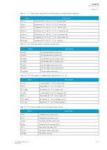
Time remaining to trip
0.000...1800.000s
When the function has detected a fault and counts down time towards a
trip, this displays how much time is left before tripping occurs.
PSx Scaled magnitude X -5 000 000...5 000
000
Displays measurement value after multiplying it the value set to
PSx
Magnitude multiplier.
PSx >/< MeasMag1/
MagSet1 at the moment
-5 000 000...5 000
000
The ratio between measured magnitude and the pick-up setting.
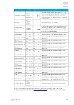
PSx >/< MeasMag2/
MagSet2 at the moment
-5 000 000...5 000
000
The ratio between measured magnitude and the pick-up setting.
PSx >/< MeasMag3/
MagSet3 at the moment
-5 000 000...5 000
000
The ratio between measured magnitude and the pick-up setting.
PSx >/< CalcMeasMag/
MagSet at the moment
-5 000 000...5 000
000
The ratio between calculated magnitude and the pick-up setting.
Pick-up
The
Pick-up setting Mag setting parameter controls the pick-up of the PGx>/< function. This defines
the maximum or minimum allowed measured magnitude before action from the function. The function
constantly calculates the ratio between the set and the measured magnitudes. The user can set the
reset hysteresis in the function (by default 3 %). It is always relative to the
Pick-up setting Mag value.
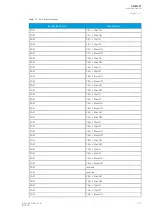
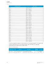
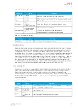
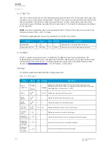
Table. 5.7 - 337. Pick-up settings.
Name
Range
Step
Default
Description
PS# Pick-up term
Mag#
0: Over >
1: Over (abs) >
2: Under <
3: Under (abs) <
4: Delta set (%) +/-
>
5: Delta abs (%) >
6: Delta +/- measval
7: Delta abs
measval
-
0: Over
Comparator mode for the magnitude. See "Comparator
modes" section below for more information.
PS# Pick-up setting
Mag#/calc >/<
-5 000
000.0000…5 000
000.0000
0.0001
0.01
Pick-up magnitude
PS# Setting
hysteresis Mag#
0.0000…50.0000%
0.0001% 3%
Setting hysteresis
Definite operating
time delay
0.000…1800.000s
0.005s
0.04s
Delay setting
Release time delays 0.000…1800.000s
0.005s
0.06s
Pick-up release delay
The pick-up activation of the function is not directly equal to the START signal generation of the
function. The START signal is allowed if the blocking condition is not active.
Comparator modes
When setting the comparators, the user must first choose a comparator mode.
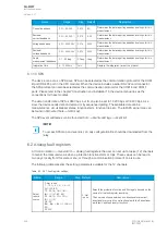
Table. 5.7 - 338. Comparator modes
Mode
Description
0: Over >
G
Grrea
eatter than
er than. If the measured signal is greater than the set pick-up level, the comparison
condition is fulfilled.
A
AQ
Q-M257
-M257
Instruction manual
Version: 2.07
© Arcteq Relays Ltd
IM00021
419
Summary of Contents for AQ-M257
Page 1: ...AQ M257 Motor protection IED Instruction manual...
Page 2: ......

