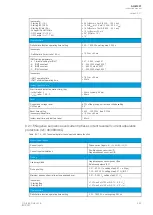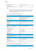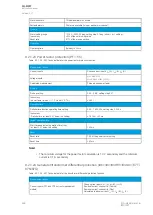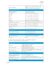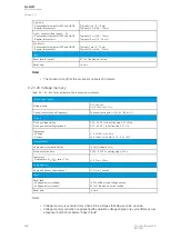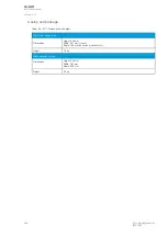
Current input magnitudes
The phase currents of the high-voltage and the low-voltage
sides.
Residual current measurement for HV/LV REF protection.
Phase currents 2
nd
and 5
th
harmonic measurement.
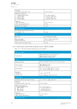
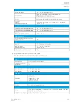
Characteristics (differential and REF)
Differential calculation mode
Bias calculation mode
Add or subtract (CT direction)
Average or maximum (sensitivity)
Idb> pick-up
Turnpoint 1
Slope 1
Turnpoint 2
Slope 2
0.01…100.00 %, step 0.01 %, default 10.00 %
0.01…50.00 × I
N
, step 0.01 × I
N
, default 1.00 × I
N
0.01…250.00 %, step 0.01 %, default 10.00 %
0.01…50.00 × I
N
, step 0.01 × I
N
, default 3.00 × I
N
0.01…250.00 %, step 0.01 %, default 200.00 %
Idi> pick-up
200.00...1500.00 %, step 0.01 %, default 600.00 %
Internal harmonic blocking selection
None, 2
nd
harmonic, 5
th
harmonic, both 2
nd
and 5
th
harmonic.
2
nd
harmonic blocking pick-up
0.01…50.00 %, step 0.01 %, default 15.00 %
5
th
harmonic blocking pick-up
0.01…50.00 %, step 0.01 %, default 35.00 %
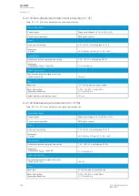
Inaccuracy:
- Differential current
±3.0 %I
SET
or ±30 mA (0.10…4.0 × I
SET
)
Instant operation time
Instant operation time >1.05 × I
SET
<40 ms (Harmonic blocking active)
Instant operation time >3.00 × I
SET
<30 ms (Harmonic blocking active)
Reset
Reset ratio: differential current
97 % of the differential current setting (typically)
Reset time
<45 ms
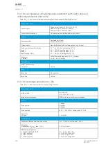
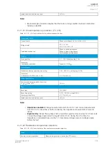
9.2.1.25 Arc fault protection (IArc>/I0Arc>; 50Arc/50NArc) (optional)
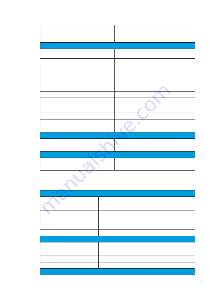
Table. 9.2.1.25 - 422. Technical data for the arc fault protection function.
Measurement inputs
Current inputs
Phase current inputs: I
L1
(A), I
L2
(B), I
L3
(C)
Residual current channel I
01
(Coarse)
Residual current channel I
02
(Fine)
Current input magnitudes
Sample-based phase current measurement
Sample-based residual current measurement
Arc point sensor inputs
Channels S1, S2, S3, S4 (pressure and light sensor, or light-only sensor)
Up to four (4) sensors per channel
System frequency operating range
6.00…75.00 Hz
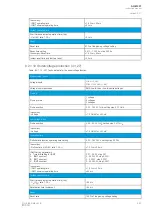
Pick-up
Pick-up current setting (phase current)
Pick-up current setting (residual current)
Pick-up light intensity
0.50…40.00 × I
N
, setting step 0.01 × I
N
0.10…40.00 × I
N
, setting step 0.01 × I
N
8, 25 or 50 kLx (the sensor is selected in the order code)
Starting inaccuracy (IArc> and I0Arc>)
±3 % of the set pick-up value > 0.5 × I
N
setting. 5 mA < 0.5 × I
N
setting.
Point sensor detection radius
180 degrees
Operation time
A
AQ
Q-M257
-M257
Instruction manual
Version: 2.07
© Arcteq Relays Ltd
IM00021
497
Summary of Contents for AQ-M257
Page 1: ...AQ M257 Motor protection IED Instruction manual...
Page 2: ......

