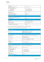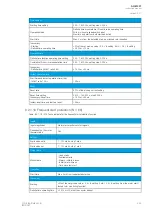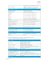
Light only:
- Semiconductor outputs HSO1 and HSO2
- Regular relay outputs
Typically 7 ms (3…12 ms)
Typically 10 ms (6.5…15 ms)
Light + current criteria (zone 1…4):
- Semiconductor outputs HSO1 and HSO2
- Regular relay outputs
Typically 10 ms (6.5…14 ms)
Typically 14 ms (10…18 ms)
Arc BI only:
- Semiconductor outputs HSO1 and HSO2
- Regular relay outputs
Typically 7 ms (2…12 ms)
Typically 10 ms (6.5…15 ms)
Reset
Reset ratio for current
97 % of the pick-up setting
Reset time
<35 ms
No
Notte!
e!
• The maximum length of the arc sensor cable is 200 meters.
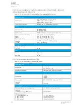
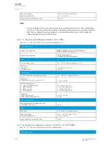
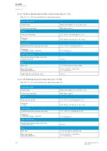
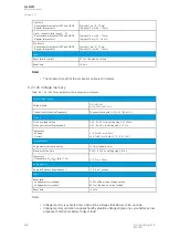
9.2.1.26 Voltage memory
Table. 9.2.1.26 - 423. Technical data for the voltage memory function.
Measurement inputs
Voltage inputs
U
L1
, U
L2
, U
L3
U
L12
, U
L23
, U
L31
+ U
0
Current inputs (back-up frequency)
Phase current inputs: I
L1
(A), I
L2
(B), I
L3
(C)
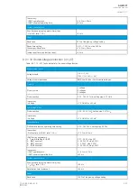
Pick-up
Pick-up voltage setting
Pick-up current setting (optional)
2.00…50.00 %U
N
, setting step 0.01 x %U
N
0.01…50.00 × I
N
, setting step 0.01 × I
N
Inaccuracy:
- Voltage
- Current
±1.5 %U
SET
or ±30 mV
±0.5 %I
SET
or ±15 mA (0.10…4.0 × I
SET
)
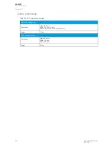
Operation time
Angle memory activation delay
<20 ms (typically 5 ms)
Maximum active time
0.020…50.000 s, setting step 0.005 s
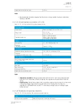
Inaccuracy:
- Definite time (U
M
/U
SET
ratio >1.05)
±1.0 % or ±35 ms
Angle memory
Angle drift while voltage is absent
±1.0° per 1 second
Reset
Reset ratio:
- Voltage memory (voltage)
- Voltage memory (current)
103 % of the pick-up voltage setting
97 % of the pick-up current setting
Reset time
<50 ms
Note!
• Voltage memory is activated only when all line voltages fall below set pick-up value.
• Voltage memory activation captures healthy situation voltage angles, one cycle before actual
activation (50Hz/20ms before “bolted” fault)
A
AQ
Q-M257
-M257
Instruction manual
Version: 2.07
498
© Arcteq Relays Ltd
IM00021
Summary of Contents for AQ-M257
Page 1: ...AQ M257 Motor protection IED Instruction manual...
Page 2: ......

