The sixteen freely configurable LEDs are located on the left side of the display. Their activation and
color (green, orange, red) are based on the settings the user has put in place in the software.
The view in the screen is freely configurable. Virtual switches and buttons can be added which can be
used to change the setting groups or control the relay's general logic locally or remotely. The status of
the object (circuit breaker, disconnector) can be displayed on the screen. All measured and calculated
values regardless of the magnitude catecory (current, voltage, power, energy, frequency, etc.) can be
shown on the screen.
Holding the II (object control) button down for five seconds brings up the button test menu. It displays
all the physical buttons on the front panel. Pressing any of the listed buttons marks them as tested.
When all buttons are marked as having been tested, the device will return back to the default view.
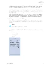
4.2 Configuring user levels and their passwords
As a factory default, no user level is locked with a password in an IED. In order to activate the different
user levels, click the LLock
ock button in the device's HMI and set the desired passwords for the different
user levels.
NO
NOTE!
TE!
Passwords can only be set locally in an HMI.
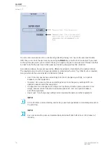
A number of stars are displayed in the upper right corner of the HMI; these indicate the current user
level. The different user levels and their star indicators are as follows (also, see the image below for the
HMI view):
• Super user (***)
• Configurator (**)
• Operator (*)
• User ( - )
A
AQ
Q-M257
-M257
Instruction manual
Version: 2.07
© Arcteq Relays Ltd
IM00021
15
Summary of Contents for AQ-M257
Page 1: ...AQ M257 Motor protection IED Instruction manual...
Page 2: ......


