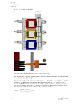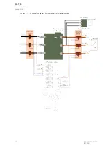
It is also Important to know the wiring of the CTs: do the CTs have a common return wire or are both
ends of both CTs wired to the terminal connector? Usually there are four wires coming from the CTs to
the terminal: in these cases the length per phase is the sum of the distance from the CT to the relay
and the distance from the relay OR from the CTs to the common coupling point. When both sides of all
CTs are wired to the relay or to the terminal, the length of the wiring is double the distance from the CTs
to the relay. If the connection is a combination of these two wiring types, the length can be estimated
by increasinf the distance in proportion to the six-wire or four-wire connection. For example, if six wires
connecting the CTs to the terminal account for 30 % of the wiring (in addition to the four wires
connecting the and the terminal), the estimated length of the wire is 1.3 times the distance between
the relay and the CTs.
The next loading factor is the resistance of the relay's measuring input. In this relay type the resistance
is 0.0005 for the current input, which gives approximately 0.001 VA with a current of 1 A. Then we
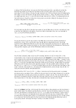
need to calculate the accuracy limit factor (ALF). This requires the CT nominal ALF value and we can
get that from the above-mentioned CT rating: the figure after P gives the current overload as a factor of
the nominal rated value and therefore gives the ALF applicable at that overload of the CT. The actual
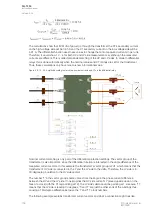
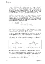
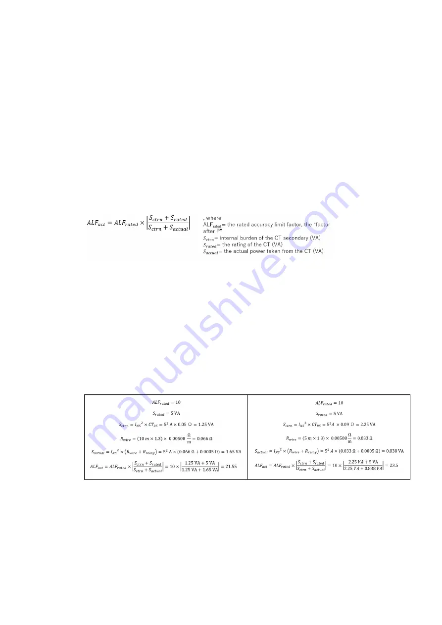
ALF can be calculated with the following common method:
The main issue with this equation is the
S
CTRN
, the internal burden of the CT secondary. The internal
resistance is related to the CT rating, to the winding length as well as to the dimensions of the wire
used in the winding. Some CT manufacturers include the SCTRN value in their product documentation.
However, as the value is only a small portion of the CT burden as a whole (the wirings cause most of it
in typical relay applications), one should not worry if the value is unknown.
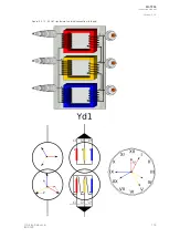
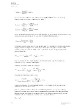
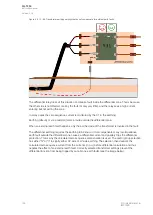
For example, let us assume that the internal resistance of the CT's HV side is 0.05 Ω and is rated 5 VA,
and that the internal resistance of the CT's LV side 0.09 Ω, also rated 5 VA. The wiring from the HV
side to the relay is 10 m and from the LV side to the relay 5 m; both sides have 30% of the wiring made
with a six-wire connection and 70% of the wiring with a four-wire connection. The wirings on both sides
are made with 4 mm
2
wires. The HV side is 150/5 A, with the protection class 10P10; the LV side is
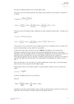
1200/5 A, with the protection class 5P10. Therefore, the actual accuracy limit factor on both sides is as
follows (the HV side on the left, the LV side on the right):
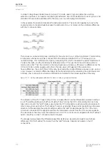
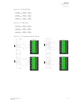
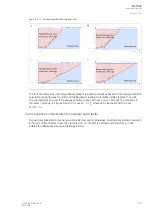
When comparing the corrected CT accuracy limit factors to the estimated maximum through fault
currents, we can see that the current will not saturate the CTs. The HV side can repeat the current
21.6 ×
I
n
, while the calculated HV through fault current is at maximum 20.2 ×
I
n
. The same is true for
the LV side where the maximum output is 20.2 ×
I
n
when the LV side CT is able to repeat 23.5 ×
I
n
.
From this we can expect that through faults will not cause problems with this power transformer and CT
combination. It also shows us that the non-biased differential stage can be set to operate sensitively
during in-zone faults. If the CTs have the possibility to saturate (that is, the calculated through fault
current is bigger than the ALF on either CT side), the setting of the instant stage must be set high
enough so that it does not operate on through fault saturation.
A
AQ
Q-T256
-T256
Instruction manual
Version: 2.06
122
© Arcteq Relays Ltd
IM00028
Summary of Contents for AQ-T256
Page 1: ...AQ T256 Transformer protection IED Instruction manual...
Page 2: ......

